• Hi Guest!
    You can help ensure that British Car Forum (BCF) continues to provide a great place to engage in the British car hobby! If you find BCF a beneficial community, please consider supporting our efforts with a subscription.

    There are some perks with a member upgrade!
    **Upgrade Now**
    (PS: Subscribers don't see this gawd-aweful banner
Tips
Tips

TR2/3/3A Beginning the TR2 Bodywork

John.

I have a question & would appreciate your thoughts.

I'm the 2nd owner of a '59 TR3A (nice survivor). The bulk of the visible rust is on the forward portion of the driver's side floor pan & where this floor pan meets the kick panel (Typical location?).

Would it make sense to make the 3" wide replacement panel from 304 SST instead of carbon steel?

As part of my inspection & mechanical restoration process (SST brake lines, etc.), I will be removing the tub from the chassis.

I have a local certified welder (& fabber) who told me welding carbon steel to stainless steel is no problem. He works mostly with ss.

I'm I missing something? Is it overkill?

BTW, your excellent photos & detailed documentation are greatly appreciated & are inspiring.

Thanks,

mgf

Stainless patches would definitely prevent any future rust outs! My TR3 was finished 5 years ago, and, unlike when it was new, it has not been driven in the rain since the restoration. I just have no reason to, as it is not a daily driver. I would imagine most restorations won't be treated to the same wet conditions they were when a young 20's something owner bought them in the 1950's and '60's either. If the stainless was cheap and available, it couldn't hurt...but I wouldn't spend significantly more to do it in my case. If I lived in the damp in Washington state, I might feel differently, though!
 
Stainless patches would definitely prevent any future rust outs! My TR3 was finished 5 years ago, and, unlike when it was new, it has not been driven in the rain since the restoration. I just have no reason to, as it is not a daily driver. I would imagine most restorations won't be treated to the same wet conditions they were when a young 20's something owner bought them in the 1950's and '60's either. If the stainless was cheap and available, it couldn't hurt...but I wouldn't spend significantly more to do it in my case. If I lived in the damp in Washington state, I might feel differently, though!

John,

Thanks for your feedback.

I have some time before I need to make a final decision.

mgf
 
I think this is the area that you are talking about? Here it is/was on my 1960.

P1070009-1.jpg


I originally created a patch for this area but then changed my mind and replaced inner/outer sills and floors...

P1070034.jpg


Cheers
Tush
 
Tush, that is interesting that yours rusted from the side inward. I guess that must be from road salt working from the outside in. Down south most of our rust seems to be from owners leaving the car out in the rain, so the floor board captures the water and is the first thing to rust through.
 
Not sure John as this car came from Colorado (never driven in Canada). I'm the third owner of it...first owner had it shipped to Japan from the factory...second owner purchased it in 1967... I bought it in 2009 (I think).

My 59 has similar rust but it is a Canadian import car that was driven hard :smile:

Cheers
Tush
 
I used mild steel for all my repairs. I cut cardboard patterns, then fitted in the new sheet metal patches and MIG welded them with butt joints which I ground flat and smooth. That was in 1988 and now with a further 114,000 miles on my 1958 TR3A, The paint is still like new.

Don Elliott, Original Owner, TS 27489 LO. I bought it brand new in May 1958 here in Montreal and it is now 58 years old. Just like new. NO ! Better that new !

Don,

Thanks for your input

mgf
 
Week 31.

I'll start out this week with a quiz. Sorry, no prizes, just the thrill of knowing that you know more than any normal human should logically know about Triumphs! Here it is:


This is the start of a small part fabrication. The riddle is to guess what these will be...I'll give hints until I finally show the finished parts.

I'll apolologize, as I am working in the O'Hare airport with an IPad, so posting is both tedious and slow. Keep checking back, as I will be posting this week in short installments. Time to get started...


I had to include this pic, to show the power of PB Blaster. No advertisement, just a product that gets results. If you remember last week, I soaked the broken windscreen bolts overnight before removing the broken stubs. When I sprayed the bolts, I took extreme caution to prevent getting the PB Blaster on the metal, as I didn't want it to cause a problem later during painting, in case I forgot to clean the area thoroughly.

Well...it didn't matter! Look at how far the PBB spread over the week. Last week it only covered about 1" around the 3 holes. Now it has spread both downward AND even upward! I got a kick out of how well it penetrates...but then I am easily amused.


The first point of business this week was that little rust through on the right scuttle corner. A small patch is in order...


Like this!


That was a quicky, so to speak.


Next is the lower right portion of the scuttle where the wing bolts up. There are some cracks to the rear, and the forward portion is eaten away.


Here I have welded the cracks back together and spliced the patch in. It's all ready for clean up with the grinder.


This pic is of the very center of the scuttle, right where the fresh air vent would be on a later TR3. You can see there was damage, and a shop previously drilled holes to pull the dent out. I started by trying to weld the little puller holes back closed so I could finish the hammer and dolly work. The problem arose when I realized I was welding into puddles of lead.

Bummer. Someone had tried to lead the area. I had to stop what I was doing and remove the lead so I could get back to plugging the holes. Just a minor set-back. I did learn that you can actually MIG weld steel into lead...The steel ends up "floating" in the molten lead, and it never reaches the underlying sheet metal. Useless lesson #1,786,987 on this restoration!

I am certain I now have lead poisoning, but being raised in the 1960's, I am also certain that I already did anyway.


As before, the solution to remove lead is just a matter of turning the part on edge and heating the lead so it runs right off. Start at the top and melt it downward.


And here is what I was left with. You can see that, even after hammering the metal straight, it is bowed outward from being stretched from the dent. To verify the stretch, when I pushed on the "bump", it would oil can inward and stay there. This will have to be shrunk.

I get the feeling that a few out there are still a bit mistified by shrinking metal, so I took the time to take a few more detailed pics of the process. I've gotta run catch a plane now, but I'll post more when I get to Kansas City later...

And, I haven't forgotten...here's your next clue...

 
Cancelled and stuck in Chicago...no surprise there for anyone who's been through O'Hare.


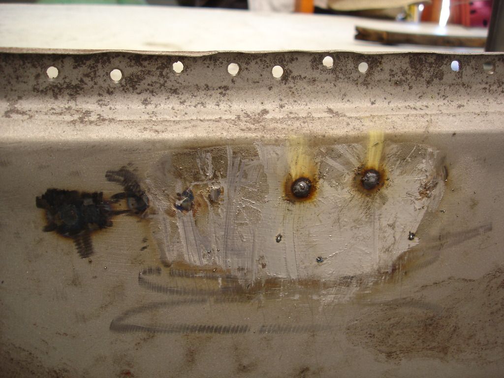
So, here is the starting point...the center of the scuttle. I have plug welded the holes that don't belong. The beads are ground flush, and the panel has been worked straight with a hammer and dolly. But, it oil cans, so some shrinking is in order.


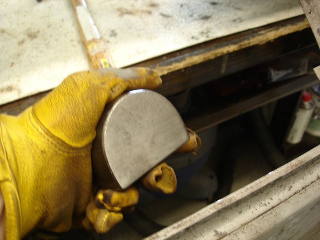
The first step is to get all your tools in line. This section of the scuttle is very near flat, so I selected a flat side of a dolly to act as the backing.


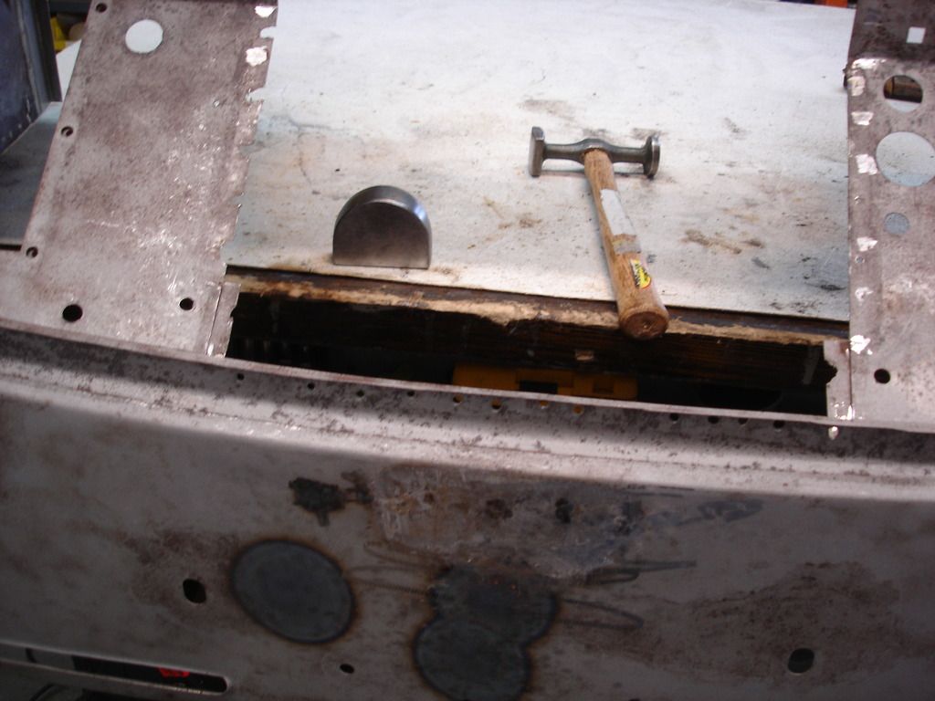
My hammer of choice is the heaviest I have with a flat head. It is very, as in VERY important to locate the hammer and dolly so you can reach them in a second or two. Decided which hand will do the hammering, and which the backing, and line the hammer and dolly for rapid use. Here I am ready for my right handed hammering.


After the first couple tries, I found myself fumbling to reach through the battery box hole, so I eventually lined them up right on top of the scuttle. The reason it is important is that you want to heat the panel to red hot, and then have time to set the torch down and start hammering before the red glow disappears.


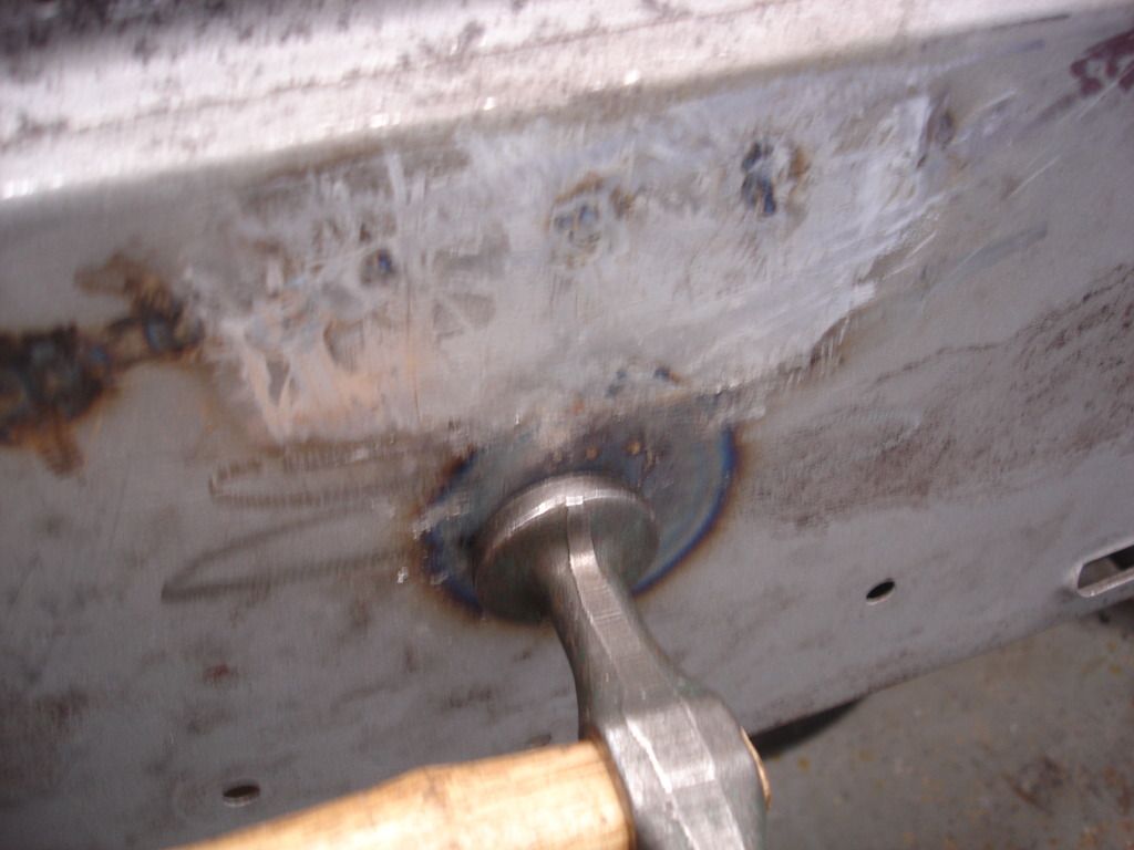
Here is the first spot for shrinking. I found it as it is the very center of the oil can. Heat it red hot, at about a 2" circle.

If you are new to shrinking, the scary part is the amount of distortion you get by heating the metal. This is a bit blurry, but in the upper area you can still see the red spot on the scuttle, and look at how far the metal has distorted outward. I would estimate it's about 1/2".


Now, once the metal is bright red, set down your torch, grab the hammer and dolly...and beat like **** trying to flatten out that distortion. Most hammer work is just gentle tapping. This is the exception...you need to beat it hard, fast and furiously for a good minute while the spot cools. You will get back to tapping later. This is a time to forge the metal in against itself like Ye Ole' Smiths used to do.


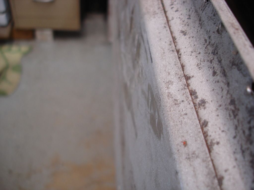
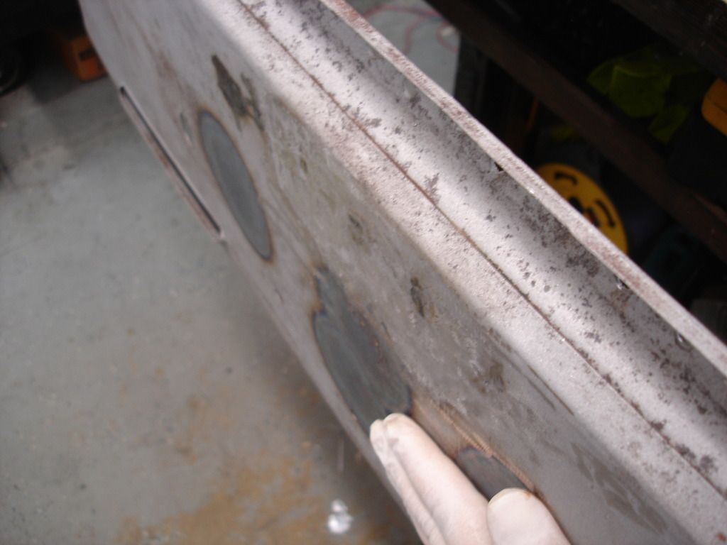
Here is the side view of that same first spot. Notice that all that distortion has flattened out nicely. But, we are not done. Now press around the spot you shrank and you will find that the oil can has moved off to one or both sides. Pick the worst spot...and do it again!


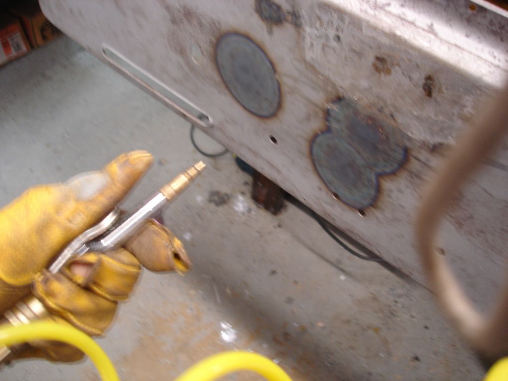
It is important to remember that when you finish beating the metal, and it has stopped glowing, that it is still extremely hot. Being hot means that it is STILL distorted! So, you have to wait for it to cool to see how the panel faired. Let it cool before you pick the next spot to shrink. In this pic I am using my air nozzle to speed the cooling process. It's pretty cool (no pun intended) watching the metal rapidly move into place as you hit it with the cooling air.


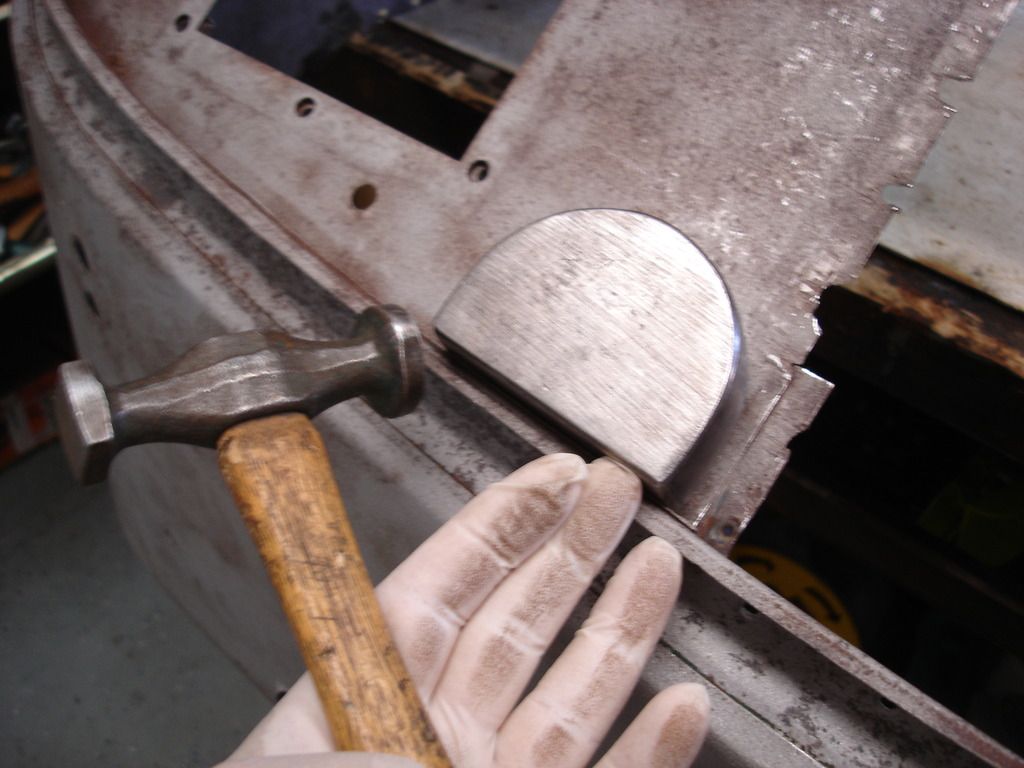
Now, once you reach a point where the panel is cool and there is no more tendency to oil can, it is time to shift back to the "tap" mode of hammering. No more hard whacking! Here I am gently working on flattening the edge of the shrunk spot, which will always come out a bit wavy. You can tell when it's flat again, because the hammering will change from a dull thump, thump, to a "ring" as the flat panel allows it to contact the dolly.


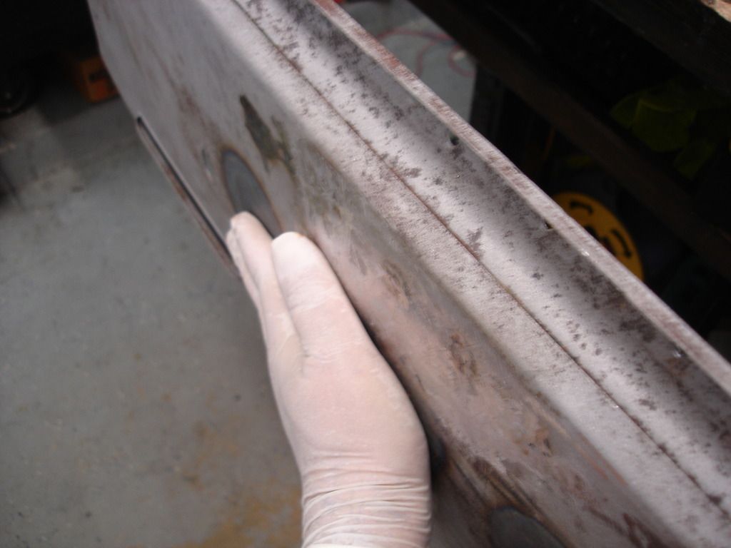
I cannot emphasize enough that learning to use your hand to determine low/high spots is absolutely essential. Here I am rubbing my hand back and forth to "feel" every wave in the panel. It will start with so much warpage that it just feels "rough". Just slow down your rubbing until you can isolate any particular high or low spot...and tap it.

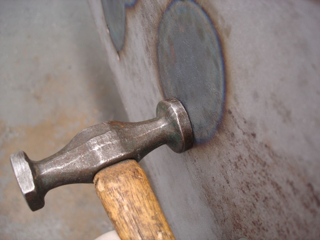
Then check some more and tap the next spot. Pretty soon you will work it down to just a handful of problem spots. And, eventually, the large head hammer seems to not help fix those spots. That means it's time to switch to a small head hammer. You have reduced the waves to small spots...so small hammer to work them.

In the top of the next pick you can see the small headed hammer I used to do the finish work. It does a better job than the large hammer in "isolating" the spot you need to move.


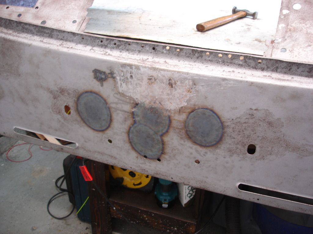
Here is the finished scuttle. It took 4 heatings and a good 2-3 hours of hammering. That sounds slow...and it is. You cannot rush bodywork.

So...that's a detailed description of shrinking. A quick note about safety. You find yourself rushing to set the torch down quickly to catch the hammering while the metal is still hot. Be careful! I used to use a torch stand, but frequently found myself rushing so fast that I could not secure the torch fast enough, and it occasionally fell. Not good! I now take a split second to shut off the torch, and then I can almost "toss" it out of the way without catching the shop on fire. Find a fast and reliable system for dealing with your torch during dry runs....before you do your actual shrinking.


The title of this section is alternative tool use. This pic shows where the inner wing is welded to the firewall. There is a decent sized dent in the wing...and it is way to close to the firewall in that area to get a dolly or hammer behind it to knock it out. A lessor bodyman than we Triumph owners would settle for bondo in this situation. But, Not we real men!


Real men use crow bars to work on cars and to settle those occasional relationship problems on the freeway.

Here I have used the flat, screw driver shaped, end of the bar to wedge it between the firewall and wing, right under the dimple. Most of you are now thinking that I can "pry" the dent out. Unfortunately, I did try that, but the firewall is too. Flimsy. I would add a new dent in removing the original. Time for some ingenuity. (That means I called my teenage son for ideas).


And...the simple solution. With the the end of the bar located on the dent, we just hammered on the bar in the direction we needed to remove the dent. The mass of the bar transmits the hits to the dent. Easy! It did take several dozen "hits"...but it worked...without bondo! A little planning can save gallons of bondo.

"Enough!! Of your verbose literary dribble!! The clue, man, what's the next CLUE!!"

Here it is...


And, at this point if you still do not recognize the parts, you might want to hand your TR2/3 restoration over to someone less socially adept and more like us no-life Triumph huggers!

No more clues...the answer awaits...
 
That's some good advice when shrinking metal, plus keep a fire extinguisher handy as well.
You are coming along quite nicely on the tr.
 
The (in)Famous Battery Box!

Rarely does a TR2/3 restoration get away without replacing the dreaded battery box. Soon, coming to a pathetic, blog like thread nearby...the secrets will be revealed!


Guess you can tell I am not a big fan of repro parts. I have found that most of them for the TR2/3 are more work fitting a repop than it is patching an original. You'll see what I mean fitting the battery box. I did buy one from Moss, and it even has the British Heritage sticker, which generally means it as good as you are going to able to find. They still leave a whole lot to be desired.

Before installation, there are several items that do NOT come with the repro battery box...for some unknown reason. So, first step is to attach the missing hardware onto the new box. Other hardware, namely the hold down straps, are inadequate on the new boxes and need to be replaced.


Here I am drilling out the spot welds holding the battery straps to the box. The original straps are made of 12 gage steel. The repop has only 20 gage straps, so they have to go. I will remove the thicker straps from the original box, as they are not prone to heavy corrosion.


Here are the straps coming off the donor car's battery box. I mentioned a few weeks ago that something was going on with this box, as it just did not look right. Now I learn why...the entire box was brazed into the car...even the hold down straps. I'm not sure if I have ever mentioned how much I dislike brazing?!?


This is a shot of the repop strap next to the original. No comparison...and that is why I am switching them out!


Because of the brazing, I had to heat the entire strap red hot and pry off the brazed metal. Uhhgg. I punched the holes into the straps to hole-weld them to the new box.


The next part that has to be either transplanted from your old box or fabricated new are the 2 instrument panel support anchors. I fabbed mine from 2" X 2" square sheet.


Now I have all the missing parts to install on the new box. So, I reviewed all my pics of the original box and welded everything back on. Everyone is up to speed on the little "T" parts...right??


Since I'm basically a lazy welder, and don't like to spend a lot of time clamping, I silhouetted the placement of each part using spray primer. I can then just hand hold the part where it goes and tack it in place.


The box came primed...so don't forget to scrape some of the paint so you can strike an arc with the welder. All you need is enough to get the arc started, then it will burn it's own area.


And...yes...those weird little parts are the wire loom ties. 1950's tie wraps!


Here is the box with the instrument panel anchors and wire straps installed.


Now, here's one facet of the box that is easy to forget about. The Overdrive solenoid actually bolts to the battery box. To prevent the screws from puncturing the back of the battery, the countersunk screws must have a recess to allow the heads to remain flat with the inside surface of the box.

Here I have drilled the 2 holes for the solenoid screws. I have selected a countersunk head wood screw that just fits the holes. I will place that screw inside the box and in each hole...back the outside of the box with a small socket, and then hammer the head to sink the head into the socket. The result is a perfect recess for the solenoid screw heads.
 
Looking good John. I bought the TRF box....I'm not sure how they compare price wise, but I think the TRF box looks to be a little better constructed and had the wire T's and angles installed.

Cheers
Tush


Now we install the box...finally. Here is the part that trips every first-timer up. If you slide the bottom of the box in first, the top of the box will not fit under the rain rail of the scuttle. And...


If you put the top in first, under the rain rail, then the bottom doesn't even come close to fitting!

Bummer.

There are many ways you can handle this problem. Most of them involve cutting metal, or even separating welds on the box. Those will work fine, but here is what I recommend:


The first step is to bend the top edge of the new box like shown here. Nothing fancy, just shove it back with your hands. It's only 20 gage metal, so it's not that strong anyway.


Now, you are closer, but it still does not quite fit.


This is one of the 2 rectangular pieces of filler metal that the factory put to fill between the firewall and the battery box. One on each side. They have to come out. As you can see from the claw marks...they fought me all the way coming out!


Finally, the new box easily slips in place. We will start the welds at the bottom to anchor it, and then we can bend the top back into alignment. Piece of cake!


I did forget to mention that I punched holes along the front edge of the new box...to aid in the welding. Here I have hole-welded that front edge into place on the firewall.


With the front edge anchored, you can simply bend the top edge back to shape. It does pick up a small wave from the bending, but a few minutes with the hammer and dolly flatten it right out.


Here I have hole welded the sides of the box, but I still have to re-install the 2 rectangular fillers at the top corners. If you look closely, you can see one of the other deficiencies of the repop boxes...


Namely, the top of the box is stamped straight across, but the scuttle is curved! That results in the center fitting well, but the sides overhang as shown here. This is where I stopped for the week, so this problem is for next week.

Until then...
 
Looking good John. I bought the TRF box....I'm not sure how they compare price wise, but I think the TRF box looks to be a little better constructed and had the wire T's and angles installed.

Cheers
Tush

That explains why the Moss box was the cheapest of the big 3! I guess less money means more work!
 
Thank you for the great education on metalwork repair.

I am going to have to use some of your photos as reference when I get to that part of my rebuild. The PO had done some fiberglass repairs and some cruddy welds. Also got the drivers side door gap messed up. Door won't fit.

David
 
John, you learned the hard way as I did. The TRF box is well worth the money in this case, it fits MUCH better. It comes with the dash support mounts and proper hold down ears for TR3. I actually trashed my moss box and purchased the TRF box on sale.
 
Back
Top