• Hi Guest!
    You can help ensure that British Car Forum (BCF) continues to provide a great place to engage in the British car hobby! If you find BCF a beneficial community, please consider supporting our efforts with a subscription.

    There are some perks with a member upgrade!
    **Upgrade Now**
    (PS: Subscribers don't see this gawd-aweful banner
Tips
Tips

90 XJS V-12 High Fuel Consumption & Low Power

Michaell, Now that you have eliminated the ECU from suspicion, it gets hairier and I am curious to try some bold steps. Take your coolant temperature sensor out of the head and measure it at ambient temmperature. It should be somewhere over 3K ohms. Now get/borrow a resistance box and divide the measured resistance by half. (should be 2k ohms or less). Dial in your half value to the resistance box and substitute it for your coolant temperature sensor. Connect one side of the box to ground and the other side to the coolant sensor lead. How does the car run now? If it is still rich then reduce the resistance box further. See if you can trick the fuel injection into not running rich. Let me know the results. If reducing the value of the coolant sensor value seems to have no effect, you better make a measurement for continuity from your coolant sensor lead to the proper pin on the ECU connector.
 
John;

It took me a while to accomplish your suggestions.

The White sensor on the left water rail that is P/N 73198 was found to have 2.883K ohms while installed and the car having set static for several days.

I found the sensor to have 4.62K ohms ambient when removed and allowed to stabalize for an hour or so.

In tracing the wiring diagrams I learned that one side of the sensor has a blue-orange wire that connects to pin 5 of the ECU. The second wire is yellow-black and connects to yellow wire of the throttle potentiometer.

I disconnected both at their respective connectors and from the sensor and confirmed that both wires were intact with 0.001 ohms or less for both wires.

I learned that the green sensor on the r/h rail is for the marelli ignition ecu and provides engine temperature. One wire is slate-yellow and the other is blue-yellow.

The green sensor P/N DAC 4737 read 2.95K installed with the engine static for a couple of days. It read 5.21K when it was removed and allowed to stabalize for an hour or so.

I have not traced the wires back to the ignition ecu yet.

I checked the resitance for the white sensor with the engine at normal operating temperature. It read 409 ohms.

I made a resistance box with parts from the local Radio Shack. I used a 5K potentiometer. It has a range of 1.1 ohms to 5.27K ohms. I made it with female pin sockets. I made a couple of short leads with male pins and used crimp on male blade connectors with the width cut down to be about the same as the male pins in the sensor. I disconnected the AMP connector and connected the resistance box in place of the white sensor,

I started with a setting of 378.2 ohms. I tried numerous settings and found that the car would not run well at below 351.7 ohms. It was not any better with higher ohm settings.

One problem that I did find and resolve was the white wire from the distributor that goes to pin 18 for the injection ECU and is the ignition signal had all but two strands broken. I spliced and soldered the wire and found that the car was smoother, but still averaging only 14 mpg.

The Harmonic balancer is an elastomeric device with the center that mounts on the crankshaft isolated from the pulley portion by rubber bonded between. The three ignition fingers that pass over the magnetic pickup at the bottom of the front timing cover are riveted to the pulley portion. I have heard that the balancers deteriorate and eventually slip with age.

If that were to happen, the ignition would appear to be correct with a timing light, but off by what ever amount it had slipped, either advanced or retarded.

So, the question is: how do I verify that the timing is where it should be? Remember, you can turn the distributor its full range on a marelli equipped car without changing the timing because the ignition ecu compensates. If the balancer has slipped, How do you know where it is set?

Could the problem be an ignition timing problem?
 
I hooked up the resistance box to the green temp sensor for the ignition to see what effect it had. I did not notice any appreciable change.

I did notice that I have white to gray smoke on the left hand bank only.

I'm going to pull the injector rail and test the injectors again.
 
I pulled the fuel rail and tested the injectors for leakage at 35 psi. I decided to test the injectors at the pressure that the injectors would normally operate at. When I tested them earlier in this thread, I used 60 psi. This time, I found the number 5A injector dripping. I replaced it with a spare that I had.

I pressurized the rail again and verified no leaks and that the spray pattern looked good on each.

For those who are wondering how you can test your injectors, I used an old hose to supply the fittings that would connect to the rail fittings. One fitting was dead end. I bought the largest inline fuel filter that I could get and connected it to the fuel line to the rail. I filled the filter with injector cleaner and then connected compressed air to the open end with a regulator to adjust pressure. I used an AMP connector to plug onto the injector with a 12 volt D.C. source with a small push switch. I bought a large glass screw lid jar and installed a grommet just big enough for the lnjector tip in the cap and drilled a 1/8" hole to vent pressure.

I just finished the reinstallation and test drive. I still have the same problem. Sluggish with slow accelleration. Trip meter still indicates about 14 mpg with much less when making any slight acelleration, it drops down to 9.

I had to swap out the max throttle switch when it broke. There is a lot of room for adjustment. It works in conjunction with the blue vacuum switch and is supposed to richen the mixture at a certain throttle opening. I can't find a good explanation of how to set it.

The sound of the exhaust has not been normal, somewhat louder, which leads me back to ignition timing. I will pull the airconditioning compressor out of the way and pull the number 1 plug and see how the timing mark aligns at TDC. I presume if the harmonic balancer has slipped as they are alleged to do when old, that the timing will be off because the three fingers on the balancer for crankshaft position will be off.

I don't know what else to try. Any ideas?
 
I'm not familiar with this particular FI system, but I know a little about FI systems in general (bosche systems specifically to some degree).

1) is this system equiped with a O2 sensor? It could be clogged with carbon from running rich, and a cheap replacement might fix your problem. I just realized there was a hole other page - duh - forget #1.
2) is there a barometric MAP sensor? I had one of these go bad before and the car it was on kept running richer and richer until it was bellowing smoke like a fire at a tire plant.
3) how is the compression? My Toyota started running rich and I could smell gas because the ECU was upping the amount of fuel because of air getting in past a leaky cylinder head. I too got around 12-14MPG with it all the way up until the headgasket finally let loose completely.
4) is there an enrichment injector that you might not have checked along with the one's on the rail?
5) is there a leak anywhere in the intake system downstream of the airflow sensor?
 
Michael, I think you're on the right track by confirming mechanical timing via #1 piston TDC rather than relying on the balancer. Curious to hear what you find there.

FWIW: I've not looked back to see if you'd pulled the dizzy apart, but they're notorious for siezed, corroded advance mechanisms.

Good luck.
 
1. Although the O2 sensors are new, you may be right about being clogged. I will pull and clean to see if it helps. Odd that the richness seems to be on the left bank only. What else can be at issue? It seems like the ECU has two separate 6 cyl. systems since there are separate O2 sensors, one on each side.

2. The ECU was just replaced during this problem with a "just rebuilt" unit to rule out MAP issues, as was vacuum leaks, some of which were found and corrected earlier in the string in the map line.

3. The 90 model year has the marelli ignition. The distributor contains nothing inside beside the rotor. Everything else is done by the ignition ECU.

4. The engine was rebuilt a year or so ago. Compression on the left bank is as follows with engine cold:

2A-195 psi
3A-200 psi
4A-205 PSI
5A-215 psi
6A-210 PSI

I don't have 1A yet since it is "so much fun" pulling the #1 plug due to the air conditioning compressor. I don't have the B bank(r/h)readings yet either but the A bank values are similar to those I had right after the rebuild.

5. The idle speed is adjusted by adding extra air. The idle remains at about 1,000 rpm, so I do not think there are any air leaks.

I will update after checking the above.
 
The weather has been cold and wet here in south Louisiana for the last week, so I did not get much done.

On Saturday, Feb 18th, I started the car and put it up on ramps in preparation for verifying the timing as discussed above. It had sat for about 5 days. Temperature was about 38 degrees F and very damp. This day the white smoke was only on the right side, with black flecks depositing on the concrete behind the r/h exhaust. I did not see any smoke on the l/h side on that day or see similar flecks, although the flecks are all over the back of the tail lights and bumper on both sides, presumably from earlier test drives.

Up until now, the problem has been predominantly on the left side. The leaking injector was found on the l/h side.

Wednesday Feb 22, I started the car again out of curiosity, because the temperature was about 60 degrees F, although still very damp. Again the richness seemed to be on the right and not the left with the white smoke on that side and black flecks (unburned gas?) being deposited on the concrete on that side, but not any on the left.

In both instances the engine was cold and I did not continue running until up to normal temperature as I do during test drives. I don't understand what would make the problem change sides like that. O2 sensors?

I will post after pulling the O2 sensors to clean them with Carburator cleaner and after verifying the timing by removing the 1A plug. I hope to have that done in a few days.

In reading up about the Power Resistor, it divides the injectors into three groups of four. Any thoughts on how to rule it out? I swapped it with a used one that I had with no observed change.

Having swapped the Fuel ECU, replaced the coolant temp sensor, power resistor, repaired several wires, replaced the O2 sensors, repaired a vacuum leak for the MAP sensor, what else is there?

There is the air temp sensor left, but how do you test it?

There has to be something that I have overlooked.

One question that I have is that I had to replace the full throttle switch which I cracked when the engine was out. I traced around the base of the switch before replacing it so that I would install the new switch in the same position. How do you check to see that it opens/closes at the correct throttle opening? I don't find any discussion of that in the manual.

The Throttle potentiometer has the correct volt reading and appears to change smoothly throughout the range of travel.

How do you check the blue vacuum swith wired in parallel with it?
 
Here is what I found, although I am not sure what it tells me.

I found oil on the L/H O2 sensor and heavy soot on the right. Cleaned both with Carb cleaner and reinstalled.

Turning the crank counterclockwise, the piston is already starting downward from TDC when the Harmonic balancer pulley alignment mark reaches the pointer.

Short of pulling the L/H intake manifold and pulling the L/H Cam Cover to install the camshaft alignment tool, with the 1A piston at TDC, how far should the pulley scribe mark be from the pointer? /ubbthreads/images/graemlins/confused.gif
 
Mike, You have covered a lot of ground since our last conversation. Right now I am working on a 92 XJS that will not start and seems to have a fault in the ignition timing. I am like you in that I have chased the problem all over the fuel injection system and the Marelli ignition. I think that the scribe mark on the harmonic damper should be under the pointer when you are at TDC. However the Marelli system has the capability of adjusting plus or minus about 37 degrees via the ECU. I am told that it will adjust for small variations even in the harmonic damper. Also the sensor magnets (three) on the damper are anchored onto the central hub so the woodruff key would have to break for them to change position. Slipping on the rubber, which is the most common damper failure, would not change the sensor measurement. If the key breaks you would know it because the entire damper would become lose. I have to admit that I am a little skeptical about what I have just covered and I want to confirm this with a contact that I have in Great Britain at AJ6 engineering. Ill try to keep you informed. Let me give you what I have tested thus far that would effect the fuel injection and/or ignition.
1. Swapped for a known good ECU (fuel injection).
2. Measured the temperature sensors. Your measurements are correct.
3. Unhooked the throttle pot to see if that made a difference.
4.Verified that all plugs were wired correctly and receiving healthy ignition spark. Changed out the Marelli cap and rotor in this process.
5. Verify that the 1A plug fires near the scribe mark.
6. Verify that the fuel injectors are being pulsed by the ECU.
7. Verify that the fuel rail pressure is about 45psi. Also verify that the fuel rail pressure regulator will hold a vacuum and not leak.
8. Check both the crankshaft position sensor and engine speed sensor are functional. (An oscilloscope to look at the wave form is used. Also the scope is useful in observing the fuel injector pulse for dwell time)
9. I am at the place where I am going to start continuity checking the sensor-to-ECU wires.
I know that you have done most of the above but I thought listing these steps might help you in pursuing your problem. Best regards, Jack
 
Mike, I have discovered with regard to our Marelli v12s that there are inaccuracies or omissions in the Jaguar literature regarding the coolant temperature sensors. There are two identical sensors on the engine. The sensor on the B bank (left) coolant housing signals the fuel injection ECU. The sensor on the A bank side signals the Marelli ignition ECU in the right footwell. Either sensor has appx 2.5K ohms at room temperature and gets less as the coolant heats. Jack.
 
Evidently, I need to go back to V-12 Remedial Class 101. /ubbthreads/images/graemlins/blush.gif Although you use the L/H cam for the tool setting cam position when setting up the timing chain, the L/H side is not the A bank. It is the B bank!!! The plug wires were in the correct place and the cap is marked 1B for the L/H front plug. So, this time I pulled the r/h spark plug and repeated the piston at TDC check again. With the actual 1A plug pulled, it is close, but I can't be sure that I don't have a few degrees of slipage. I have located a harmonic balancer and will purchase it. I want to set both side by side to see if there is evidence of slipage.

I am toying with the idea of installing an earlier distributor and bypassing the Marelli ignition all together to see if I can isolate this as a timing or fuel injection problem. That way, I could actually set the timing with the distributor. What is the second coil for on earlier cars? I still have to figure out where I will "tap in" for power for the amplifier as well. Thoughts on this?
 
I have thought of PERMANENT conversion of the Marelli to the earlier model that is HEI. The HEI is very self contained and would operate with only 12 volt ignition switched voltage being furnished. The crankshaft position and speed sensors would not be required. The HEI would require a distributor, a conventional coil and the ignition amplifier set up. The problem comes in because the Marelli ECU takes the crankshaft position signal and furnishes it to the fuel injection ECU that generates the fuel injector triggers. The FIECU with the HEI system uses the trigger signal from ignition amplifier which is a different wave form. My guess is that the FIECU does not interchange between those models. If you are interested in trying this conversion I will contact AJ6 engineering in Great Britain and run this situation by them. I was advised that it is not possible for the sensor magnets to slip in position if the rubber allows the harmonic dammper on the crankshaft to slip. If the key in the crankshaft allows the slippage the maagnets would slip but the entire damper assembly would be lose on the crankshaft. Before you get another Marelli damper, take a hard look at the one you have and particularly the key that fixes it to the crank. Let me know what you find out. Jack
 
P. S. The second coil on the radiator brace serves no purpose that I know of for earlier models. It must have been a spare for the very early models. I dont believe that a second coil was used prior to the Marelli. My XJS is a great running car so I intend on making a comparison study between the ignition timing on mine and the 92 that wont run. If the genie comes out of the bottle you will be the first to know. Jack
 
Too late to stop purchase of another damper. Money was sent last Friday.

I already have a distributor, HEI black box and a coil from an engine that I had purchased with intent of rebuilding in my spare time (like I actually have any). What sort of things would I look at to ensure these parts are good?

I expect the damper to arrive later this week and will report what I see concerning the position of the keyway on both balancers with them sitting side by side.

Somewhere in the Kirby Palm book is a discussion about the damper slipping a few degrees and creating timing problems, but not being loose on the crank. I will try to find it again and refer you to the page. It was interesting reading. Mine does show some signs of rubber deterioration, but up to now have not had anything to compare it to.

I am interested in what part number Fuel ECU would be needed to swap over to the earlier ignition.

Had I not had trouble getting the 5-speed transmission to engage the pilot bearling when I changed the clutch, I would not have been embroiled in this mess. The car was running great until I had to change the clutch for slipping.

The onset of my problem has to have something to do with having disconnected everything when I pulled the engine to reinstall the tranny and reinstalled the whole unit. Is it possible that the harmonic balancer was bumped during removal and installation? heck yes! The Max Throttle Switch that rides on the turntable cam was damaged by a chain during engine removal, and the connection for the front magnetic pick-up end damaged because the wire was not disconnected when the harness for the two radiator support mounted ignition amplifiers was moved out of the way resulting in installation of a new pickup.

I traced the base of the broken Max Throttle switch before replacing it, but have not been able to find a write-up in the manuals to explain how to set that switch. It is intended to enrich the mixture when the throttle is opened wide, so I have never rulled out its adjustment as a part of the problem. There should be some way to determine the Throttle pot voltage desired for when the switch changes position or some other means to set when it richens the mixture. Someone would have to measure that on a car that is running well. (hint, hint)

After systematically looking at everything in the fuel and ignition systems, there are very few variables left. One is the crank pulley.

Since we cannot tell for sure if this is ignition or fuel related, that is part of why the answer is so elusive.
 
Mike, I can get the HEI ignition fuel injection ECU Jag number but that is not the problem,. In order to trade the ECU in order to accomodate the HEI ignition you would have to run the ECU cable from the engine compartment to the boot where the ECU lives. You could not use the Marelli type cable because the wire purposes and routing is different. That is not easy. I'll look at making the throttle pot measurement when the max throttle switch closes.
 
Thanks!

I expect the used harmonic balancer to arrive early next week. So, I'll stay the course and wait for it to arrive and see what the relationship is between the keyway and the three fingers.
 
I have been following your opus for the last couple of months.I think I would have been wrench throwing by Thanksgiving. Congratulations on that level of patience.


If you pulled a functioning engine and then get this problem it's going to be a pinched wire, broken wire, something like that. Your max throttle switch, can you just disconnect it from the linkage? All it does is send a signal to the ECU to go full rich when you floor it. If it is at the less than max position the engine should run correctly up until full throttle, then misfire or go flat. Can you measure the resistence thru the switch to see if and when it changes? It should.

I think it's a fuel problem, the ECU is getting a signal from one of sensors to go rich. Coolant temp sensor will double or triple the fuel flow during warm up. On the Ford ECC III, the air charge temp switch will cause the ECU to go full rich if it's covered in gunk. Tech I used to know said he called Dearborn engineering about it. They said the switch had about 3-5% change authority and couldn't cause the ECU to go full rich. Well he fixed about a dozen cars with symptoms like yours by changing it. If Ford's guys can screw up like that, Jaguar might too.

I don't know if Jaguar ever had a scanner for this car, that would be worth the money to have somebody run a scan if they did. You can see what the computer is seeing from the sensors and how it is changing the timing and fuel flow and all the rest of what it does. That would be my suggestion as to where to go next. Look at the harnesses really well to see if you messed up something there. I created a no-start once on a HEI ignition. I had the distributor cap off and pulled to one side to find tdc on a new engine. The cap fell back into the rotor while I was cranking the engine and it jerked hard enough on the HEI harness to break a wire. Took me a while to find it, HEI had only been around for a couple of years at the time and our manuals didn't have any info about troubleshooting it.

Have you tried putting a vacuum gauge on it? Low tech but if you get 16-17" of vacuum at idle you have good timing on the ignition and cams.

Good luck, Ken
 
Back to the Drawing Board!

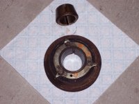
The used Harmonic balancer arrived. Photo depicts the rear side. John Farrington's source was correct. The three fingers are attached to the part of the balancer that attaches to the crank.

The rubber that has been the basis for discussion is visible in the photo arround the outer edge of the finger ring. Only the outer portion of the balancer - the actual pulley part, is dampened by the rubber.
 

Attachments

  • 185095-HarmonicBalancer.jpg
    185095-HarmonicBalancer.jpg
    144.1 KB · Views: 188
I'm not sure how people attach photos so that they appear on screen. I have a photo of the used balancer , but you have to click on the word attachment in the post above to see the photo.
 
Back
Top