Hey Guest!

 Hey - did you know if you click on the title of a thread it will take you to the first unread post since you last visited that thread?
 but were afraid to ask:
  STOP!! Never post your email address in open forums. Bots can "harvest" your email! If you must share your email use a Private Message or use the
  smilie in place of the real @
 Pretty Please - add it to our Events forum(s) and add to the calendar! >>
TRopic6
Jedi Warrior
Offline
Holy Moly Brah, those points are pitted to 'da max. Actually I ran them till they were worse than that on my TR4 back in college. She'll run with 'em like that but it won't do the timing any favors. New points are in order and you can't go wrong with Jeff at Advanced Distributors. I use Amazon Prime to get stuff to Hawaii with free shipping; try looking up LU1617 on Amazon (made by Standard Motor Products - US made). But your FLAPS probably has them too (or a Chinese variant...).
You get full voltage at the ballast wire with no load, then the voltage will drop with current flow. If you have a meter you can measure between the cut end and the white wire over at the fusebox; I got about 5 ohms on my cheap meter. You may get less because your wire is a little short (remember, this a family forum, folks...)
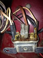
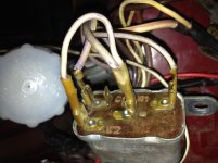
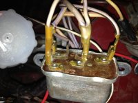
That wire originally went to the coil + terminal, connected to the same female terminal as the white/yellow wire. There are a few things to consider before hooking it back up, and someone cur it for a reason. The original starter relay had two independent 12V outputs: 1 to the starter solenoid and one to the coil.
When running off the ignition circuit, there is 9 or so volts at the coil + terminal from the ballast wire, which is connected to the white/yellow wire. If the other end of the white/yellow wire is connected to something, there will be current flow in the white/yellow wire whenever the car is running. A shorted starter relay might do it, or if someone used a single throw relay to replace the Lucas starter relay, there can be current flow through the white/red wire to the solenoid. Probably more that you need to know, but can you post a picture of your relays?
Jeff
You get full voltage at the ballast wire with no load, then the voltage will drop with current flow. If you have a meter you can measure between the cut end and the white wire over at the fusebox; I got about 5 ohms on my cheap meter. You may get less because your wire is a little short (remember, this a family forum, folks...)
That wire originally went to the coil + terminal, connected to the same female terminal as the white/yellow wire. There are a few things to consider before hooking it back up, and someone cur it for a reason. The original starter relay had two independent 12V outputs: 1 to the starter solenoid and one to the coil.
When running off the ignition circuit, there is 9 or so volts at the coil + terminal from the ballast wire, which is connected to the white/yellow wire. If the other end of the white/yellow wire is connected to something, there will be current flow in the white/yellow wire whenever the car is running. A shorted starter relay might do it, or if someone used a single throw relay to replace the Lucas starter relay, there can be current flow through the white/red wire to the solenoid. Probably more that you need to know, but can you post a picture of your relays?
Jeff
Last edited:

.jpg")
.jpg")