• The Roadster Factory Recovery Fund - Friends, as you may have heard, The Roadster Factory, a respected British Car Parts business in PA, suffered a total loss in a fire on Christmas Day. Read about it, discuss or ask questions >> HERE. The Triumph Register of America is sponsoring a fund raiser to help TRF get back on their feet. If you can help, vist >> their GoFundMe page.
  • Hey there Guest!
    If you enjoy BCF and find our forum a useful resource, if you appreciate not having ads pop up all over the place and you want to ensure we can stay online - Please consider supporting with an "optional" low-cost annual subscription.
    **Upgrade Now**
    (PS: Subscribers don't see this UGLY banner)
Tips
Tips

TR6 1974 TR6: Ballast vs Non-ballast system. A look at the wiring.

2wrench

Luke Skywalker
Country flag
Offline
photo.jpg

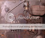
In this photo note the ballast resistor has two wires to it. I will refer to them as left and right. The wire on the left appears to be white with a black stripe. Notice that wire loops upward and attaches to the lower right-hand side of the fuse box. (This wiring does not appear to be original.) Notice, as well, the wire attached to the ballast resistor at the right is green with a small black stripe. This green wire with a black stripe is outside of the wire harness and attaches to the positive side of the coil.

My car has run fine with this wiring....but has been failing to start, especially after a drive and a park in the garage.

My coil has the white/yellow from within the harness attached at the positive side of the coil, as it should. Negative wire from coil to the distributor is
attached, as it should be.

What I am missing is a white and pink wire coming from the ignition switch, as is shown in my Dan Masters reference on wiring. It seems I should have the yellow and white and the pink and white at the positive terminal of the ignition coil.

Is this present wiring working as a 12 volt non-ballasted system because it is wired weird, or is it wired outside the harness with wrong colored wires, but still wired to work properly as a ballasted 6 volt coil?

Testing with an ohm meter has suggested that the coil is putting out less than the 6 to 9 ohms expected. I am getting between 5.3 to 5.8 at best.

I have some suspect that improper wiring is ill-affecting the condition of my coil and points and causing the car not to start.
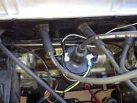
photo 2.JPG This photo shows the white with black stripe attached to the negative side of the coil to the distributor. On the positive side of
the coil is the white and yellow wire as well as the strange green with black stripe wire. Note: The wire colors are difficult to recognize as they are old and faded. Any help is appreciated.
 

TR3driver

Great Pumpkin - R.I.P
Offline
What of the white wire that appears to come from the harness to the coil?

Did you remove a wire from the fuse block terminal opposite the white/black?

5.3 to 5.8 is close enough, IMO, but indicates you have a coil that does not want an external ballast resistor.

Depending on the answer to the questions above, I suspect that someone tried adding an external ballast (perhaps the resistance wire inside the harness is broken), then later abandoned the idea (but left the components in place).

Turn the key on, turn the engine until the points are closed, then check what voltage you find at each coil side terminal (to ground). That will tell you more about what is going on.
 
OP
2wrench

2wrench

Luke Skywalker
Country flag
Offline
What of the white wire that appears to come from the harness to the coil?

Did you remove a wire from the fuse block terminal opposite the white/black?

5.3 to 5.8 is close enough, IMO, but indicates you have a coil that does not want an external ballast resistor.

Depending on the answer to the questions above, I suspect that someone tried adding an external ballast (perhaps the resistance wire inside the harness is broken), then later abandoned the idea (but left the components in place).

Turn the key on, turn the engine until the points are closed, then check what voltage you find at each coil side terminal (to ground). That will tell you more about what is going on.

"What of the white wire?" That white wire is the white and yellow coming from the C4 post of the starter relay, and appears to be appropriate, per the Dan Masters' electrical wiring diagram for a ballasted system. (Note: I did not remove tape and follow this wire from junction to junction, but it looks like the same wire at each end.)

As to the question: "Did you remove a wire from the fuse block terminal opposite the white/black wire," the answer is no, I did not. But, we must keep in mind, we did rebuild my engine and things could have been moved around, etc, as well as I just do not know the complete history of the previous owner. (Typical, I suppose.)

I am thinking that this puppy may be wired somehow bypassing the ballast, therefore, with the ballasted 1.5 ohm coil, is messing up the points or the ballast itself. I just don't know. Points do not seem to show signs of burn, though.

Thanks for your response, Randall, and your help. I am entertaining in my home and watching San Francisco 49'ers playing football. When I can catch some time, I will close the points and check the coil posts, as you have suggested. Again, thanks for your help.
 
OP
2wrench

2wrench

Luke Skywalker
Country flag
Offline
There is so much complex stuff going on re wiring..... I just want to reiterate, that this ballasted system should have a pink/white wire attached at the coil, which is power from the key ignition switch. I just do not have this wire connected on my car. Makes me wonder if the fuse block black and white wire is supposed to be providing that power as an after fix, but it is just not wired to do the job. Does anybody have a picture of original wiring showing a pink and white wire connected at the coil?
 
OP
2wrench

2wrench

Luke Skywalker
Country flag
Offline
Randall: I have checked the readings with my voltmeter and with the points closed, the coil reads at each post 0, (zero.) I went ahead and checked each post with the points open and each post reads 1.6 ohms, respectively. What do you make of it?
 

TR3driver

Great Pumpkin - R.I.P
Offline
Are you measuring from each post to ground? Or from post to post?

Maybe I missed something; does the engine run at all now? I don't see how it could with no voltage across the coil.

My guess is that there is wrong connection (or a missing wire/jumper) at the fuse block, since I don't see any connection to the white/black wire, or any other way for the coil to be getting power. This setup would make a lot more sense if the white/black wire was on the terminal under the white wire (which should be unfused power from the ignition switch). Then the white/black would carry power to the ballast resistor and on to the coil.
 
OP
2wrench

2wrench

Luke Skywalker
Country flag
Offline
I am measuring from one post on the coil and to a ground; so, coil positive post and grounded; negative post and grounded. It has occurred to me the thought that the black and white's wire's intent was to put juice through the ballast resistor and onward. I am reluctant to do much on my own, as you know my novice level mechanic.
Sounds like we may be thinking alike.

So do you think I should simply try moving the black and white wire onto a "hot" paddle on the fuse box? If so, there are two rows of
paddles, top and bottom. So if a paddle is hot (power in) on the upper right, will the opposite paddle on the lower left then also be hot?

And to answer another question you asked: The car is not starting and running now. A mechanic helped me, put a new 1.5 ohm coil in the car with a new resistor to the coil. The car started and ran well all day, driven over 100 miles. Came home, parked it. Turns over -- does not start.
 

dklawson

Yoda
Offline
When measuring coil voltages you must be aware of whether the points (or ignition module) are conducting or not.

If the points/module are "open" then coil (+) will measure 12V when the ignition switch is in the run position.
For the same condition (points open) coil (-) will ALSO measure 12V.
This is true regardless of standard or ballast ignition system IF the coil's primary windings are intact.

When the points are closed, coil (+) to ground will measure 12V for a standard ignition system and 6V to 9V for a ballast system.
When the points are closed, coil (-) to ground will measure 0V regardless of ignition type.

I did not notice in the posts above whether you were using points or an electronic ignition. If you have fitted an electronic ignition, you need to supply it with a full 12V, not the reduced voltage that a ballast ignition system will have. If the electronic module is supplied via a ballast power supply there may not be enough voltage to operate the electronics (no spark).

You said you and the mechanic installed a new 1.5 Ohm coil with new ballast resistor. Make sure that your supply to the ballast resistor has a full 12V on it. If you are using existing wiring (and IF the pink wire is present inside the harness) you might be supplying the coil through two series resistances and therefore... the coil voltage may be too low. However, if the ballast bypass wire (white/yellow) from the solenoid is intact, the engine should still start... but stop as soon as you release the key.
 

TR3driver

Great Pumpkin - R.I.P
Offline
So do you think I should simply try moving the black and white wire onto a "hot" paddle on the fuse box? If so, there are two rows of
paddles, top and bottom. So if a paddle is hot (power in) on the upper right, will the opposite paddle on the lower left then also be hot?
Yes, I do.
The top and bottom paddles on each side are directly connected together. So if you move the white/black to the paddle under the white wire, it should get unfused 12v with the key on.

The two sides of the fuse block are connected by the fuses. So If you want to have a fuse for the ignition, you could install a jumper from the paddle under the white wire over to where the white/black is connected now, and move the white/black to the other side. Here's a photo from my TR3, showing how I "daisy chained" the input side of the fuses.

But in your case, it's probably more trouble than it's worth.
 
OP
2wrench

2wrench

Luke Skywalker
Country flag
Offline
Doug: I am cutting and pasting some of your post as follows:

"You said you and the mechanic installed a new 1.5 Ohm coil with new ballast resistor. Make sure that your supply to the ballast resistor has a full 12V on it. If you are using existing wiring (and IF the pink wire is present inside the harness) you might be supplying the coil through two series resistances and therefore... the coil voltage may be too low. However, if the ballast bypass wire (white/yellow) from the solenoid is intact, the engine should still start... but stop as soon as you release the key."

For clarification, the mechanic installed a 1.5 ohm coil with a new resistor to the coil. Also, for clarification, my car does have points.

So I jumped the white and black wire to the paddle below the white wire on the fuse box, as both you and Randall have suggested I need 12V to the ballast resistor. This makes sense to me. I have verified 12 volts through and up to the "positive" side of the ballast resistor. 6 volts are present (with key on, of course,) on the exiting side of the ballast. Seems good so far. I will have to check readings for points open/points closed, as you suggest. That said, I have made these changes supplying power to the ballast and turned the car over and she still did not fire. I will do readings, once again, and advise.

Also, Doug, I am not understanding how a pink and white wire being present in the harness, but not attached at the coil, can affect things. If, somehow, it does, I suppose I will have to tear my wiring harness apart in search of the pink and white. Gentlemen, other questions come to mind, like whether the points are bad. Also, I suppose flooding could also stop her from firing, in which case I'll have to clean the plugs, I suppose.

Thanks for your time and your interest. It is much appreciated.
 

TR3driver

Great Pumpkin - R.I.P
Offline
That said, I have made these changes supplying power to the ballast and turned the car over and she still did not fire. I will do readings, once again, and advise.
Certainly could be other problems as well. In fact, since there had to be power to the coil for it to run at all, I suspect that the wire got inadvertently moved during the troubleshooting process and you are now back to where you started, looking for why it wouldn't start the next day.

My next steps would probably be to verify spark at a plug, and if that looks OK, try giving it a blast of carb cleaner down the carb throats (as starting fluid) and then immediately trying to start it. If it starts and dies, you've pretty much confirmed a fuel problem.
 
OP
2wrench

2wrench

Luke Skywalker
Country flag
Offline
With power supplied to the ballast with points open: 12.2 volts to both negative and positive poles of the coil.

With points closed: 5.6 to the positive side of the coil.

With points closed: .2 to the negative side of the coil.

Things seem more as they should be, with one exception: The .2 to the negative side of the coil.
 

TR3driver

Great Pumpkin - R.I.P
Offline
That's about right. The points do have some small resistance.
 
OP
2wrench

2wrench

Luke Skywalker
Country flag
Offline
Randall: So my car has original carbs. In order to shoot in the cleaner, I suppose I would remove the air cleaners and, what, lift the pistons and shoot in the carb cleaner? I am sort of anticipating a good spark at a plug. Top side of carb is filled with oil. Now I'm really showing my ignorance. Suppose I'm used to American made carbs.
 

TR3driver

Great Pumpkin - R.I.P
Offline
Yup, that's the idea. If your carb cleaner has a nozzle, you can just poke it under the pistons.
 
OP
2wrench

2wrench

Luke Skywalker
Country flag
Offline
Okay, Randall. I will get to the next steps tomorrow. Thanks to you responding gentlemen and to Basil for the Forum. I will proceed as advised and update you. Thanks again.
 

poolboy

Yoda
Country flag
Offline
I think I'd get a 3.0 ohm coil and do this, if you can, according to Dan Masters.
"....with the '74 - '75 TR6. The resistor bypass wire from the starter relay to the coil (white/yellow) can simply be lifted from the relay terminal and moved to the fuse box terminal where the white wire is attached. The relay is located very close to the fuse box, and unless someone has modified the car with additional accessories, there is a spare terminal by the white wire that can be used."
OR
Run a wire from the + terminal on a 3.0 ohm coil to the vacant spade ("paddle") on the fuse box where there is a white wire.
From that set up you can troubleshoot any other problems, knowing that at least that much is correct.

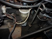
You mentioned the top side of the carb is filled with oil..hopefully only the damper well contains oil:
 

TRopic6

Jedi Warrior
Country flag
Offline
Aloha Dennis,
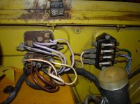
You're getting great advice from the experts. FWIW, here is a shot of the ballast wire going to the coil on my 74.5 parts car. Whatever red/pink insulation it had has crumbled and the resistance wire is exposed. This is the wire that powers the coil for normal running. For starting, the white/yellow wire supplies 12V from the starter relay. I took a shot of that as well. Your starter relay is out of the shot - where does the red wire come from?

JeffTR6 Starter Relay.jpg

TR6 Ballast wire.jpg
 

dklawson

Yoda
Offline
Sorry Dennis, I didn't mean to confuse you with my comments about the pink wire. They were more for background information.

What I really should have stressed is that on cars with Lucas ballast ignition systems the pink wire is a potential problem area. Most people either convert to use an external ballast resistor (as you have done) or switch to a standard ignition system as Poolboy suggests.

Your voltages sound appropriate to me and therefore it sounds like the point and condenser should be OK. I know you are not getting spark. Therefore, make the following test. Turn the engine over by hand until you see the points are open. Remove the coil wire from the center of the distributor cap. Place the disconnected plug wire end close to the engine block but with a small gap to anything metal. Switch on the ignition and insert the tip of a flat bladed screwdriver between the points gap. Now remove the screwdriver quickly. Repeat the insertion and removal several times. Each time you remove the screwdriver from the points you should see a spark jump from the coil wire to the engine block. Let us know if you find you have spark using this test.
 
OP
2wrench

2wrench

Luke Skywalker
Country flag
Offline
Aloha, and thanks for the pictures. In answer to your question: "Where does the red wire come from..."

The red wire you ask about is something a mechanic added when he was trying to repair my overdrive, which went in-op. Seemed to be a makeshift sort of setup going from the fuse to a relay that seemed to be just sort of sitting on my transmission. He told me my car was repaired and I could go pick it up. After I arrived, the car was not repaired and this wiring is what I am left with. Another repair for another day. The mechanic's guarantee was: "if it isn't fixed, you owe me nothing." So I took him up on his guarantee.
 
Similar threads
Thread starter Title Forum Replies Date
L For Sale 1974 Tr6 for sale Triumph Classifieds 0
A For Sale 1974 TR6 Triumph Classifieds 1
Marvin Gruber For Sale 1974 TR6 for sale, $7200 Triumph Classifieds 3
H TR6 1974 tr6 allison xr700 Triumph 12
S TR6 1974 TR6 Rear Brakes w/o hydr. press. Triumph 6
H TR6 1974 tr6 stromberg 175 cd-2 choke Triumph 2
L TR6 1974 Tr6 ignition switch Triumph 3
T TR6 ajustable training arm brackets--- 1974 TR6 Triumph 14
H TR6 1974 TR6 clutch noise when pedal is depressed Triumph 3
Gerry M TR6 1974 TR6 Wheel lug torque Triumph 4
W TR6 Question on Steering Wheel Puller for 1974 TR6 Triumph 10
G TR6 1974 TR6 distributor advance spring specs Triumph 6
2 TR6 Price Reduces on 1974 TR6 W/Ovewrdrive. excellent Triumph 0
TR6BobNF TR6 1974 O/D TR6 For Sale in Newfoundland Triumph 1
I TR6 1974 tr6 Triumph 2
W TR6 Tr6 1974 Distributor Triumph 7
RynoBoy74tr6 TR6 1974 TR6 clutch adjustment Triumph 11
T TR6 1974 TR6 coil question Triumph 3
N TR6 need the carb mounting stud size for 1974 TR6 Triumph 14
2wrench TR6 Which water pump for my April 1974 TR6 Triumph 3
2wrench TR6 1974 TR6 Engine Rebuild and/or Repair Triumph 26
2wrench TR6 1974 TR6 heater hoses to firewall or bulkhead. Triumph 12
T TR6 Swapping 1974 TR6 fenders on to my 71 TR6? Triumph 5
D Trying to get back working on the 1974 Midget Spridgets 5
wkilleffer MGB 1974 MGB clutch master cylinder questions MG 1
VeeCee MGB 1974 MGB Roof Installation MG 0
D For Sale 1974 triumph spitty davidschab60@gmail.com Triumph Classifieds 0
J 1974 Jensen Other British Cars 22
Prof. T Wanted 1974 - TR 6 Front Chrome License Plate Holder Triumph Classifieds 1
CJRams For Sale 1974 Rolls Royce Silver Shadow - low mileage, all original Other British Classifieds 0
C For Sale 1974 TR-6 Project car for sale whole Triumph Classifieds 0
P MGB 1974 MGB front spring length. MG 0
wkilleffer MGB 1974 MGB SU fuel pump voltage issue MG 11
A MGB MGB 1974 windscreen centre rod replacement MG 5
R SOLD!! 1974 Jensen Healey Other British Classifieds 0
bravenrace For Sale 1974 TRV 2500M FOR SALE Other British Classifieds 2
HAN5L778 MGB 1974 1/2 MGB Project car MG 0
krswen For Sale 1974 Panther J72 Other British Classifieds 4
J For Sale 1974 Spitfire for sale Triumph Classifieds 0
S For Sale Austin Healey Sprite and MG Midget Factory Body Parts Manuals - 1958 - 1974 Austin Healey Classifieds 0
S For Sale MG Midget Workshop Manual on CD/ROM - 1962 - 1974 Models MG Classifieds 0
S For Sale Austin Healey Sprite and MG Midget Factory Workshop Manual on CD/ROM – 1962 - 1974 Spridgets Classified 0
S For Sale Austin Healey Sprite and MG Midget Factory Workshop Manual on CD/ROM – 1962 - 1974 Austin Healey Classifieds 0
A 1974 2500M Spring Rates TVR 6
C I'm looking at a 1974 MG Midget [chrome bumpers with black sabrinas] Spridgets 9
B 1974 Midget Spridgets 6
jmayzer For Sale 1974 MG Midget Mk III [Maryland, USA] Spridgets Classified 1
J MGB 1974 1/2 MGB gasoline type MG 5
M 1974 Jensen INterceptor electrical help needed Other British Cars 8
wkilleffer MGB 1974 MGB convertible top anchor bar size MG 4

Similar threads

Top