• Hey Guest!
    British Car Forum has been supporting enthusiasts for over 25 years by providing a great place to share our love for British cars. You can support our efforts by upgrading your membership for less than the dues of most car clubs. There are some perks with a member upgrade!

    **Upgrade Now**
    (PS: Upgraded members don't see this banner, nor will you see the Google ads that appear on the site.)

1940 Stearman restoration (moved from Triumph forum so all can enjoy)

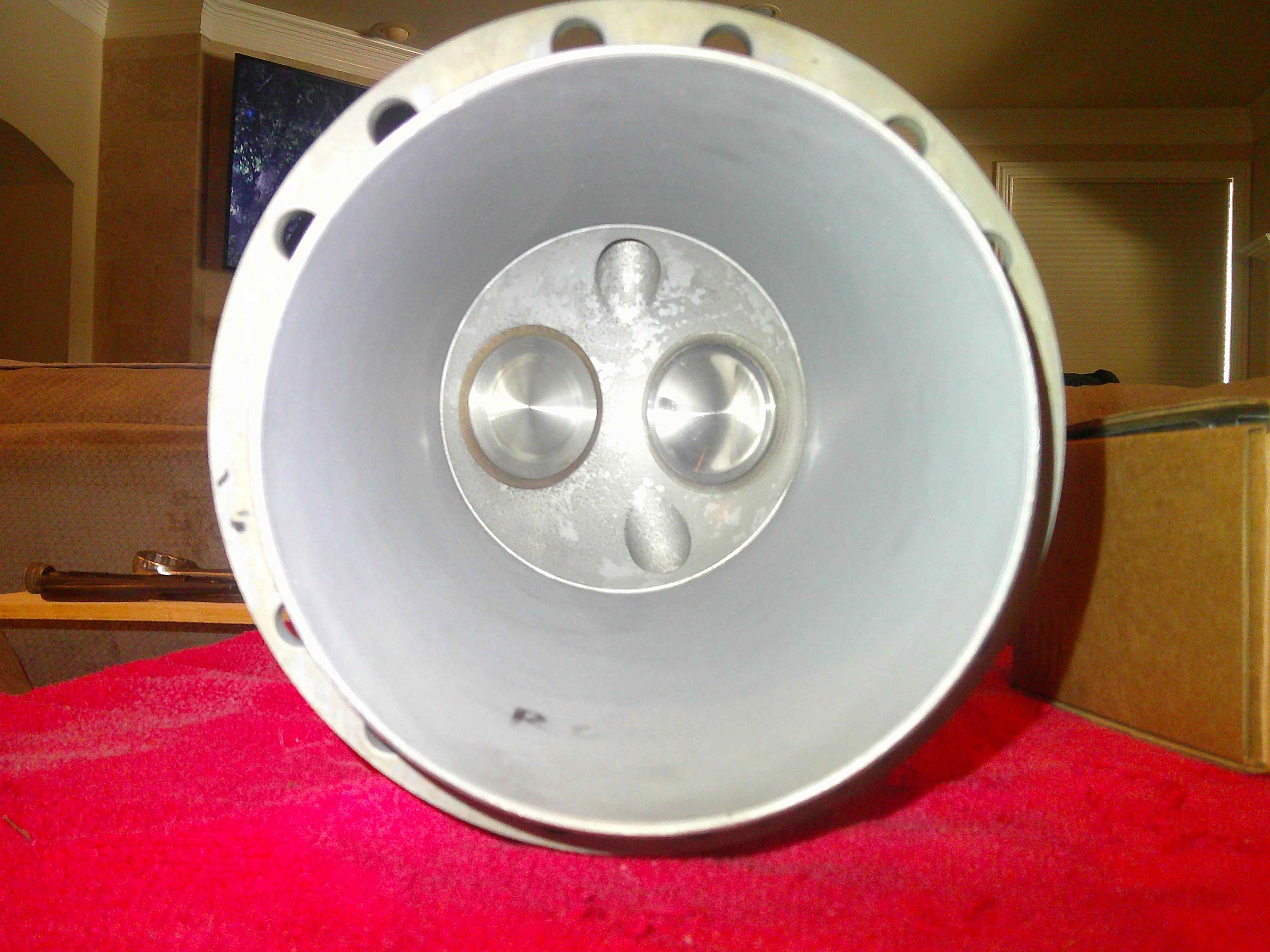
Here is a pic of the inside of the freshly rebuilt cylinders...not by me!?! I finally decided the originals with the cracked fins were not worth the effort. Boy, it is nice looking a clean parts for a change!

6.JPG


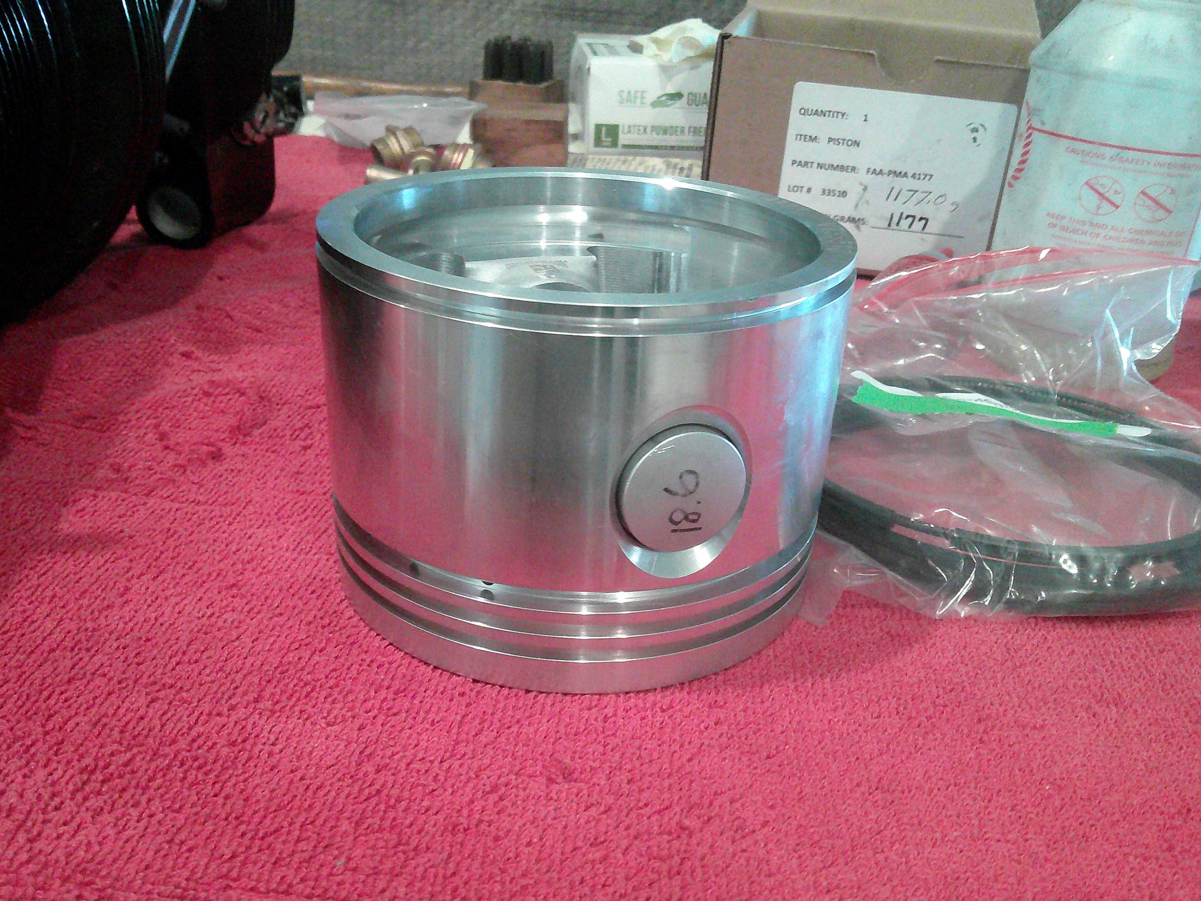
Here is a 5.25" piston to fit! This engine is a lot of cubic inches for relatively low horsepower.
7.JPG


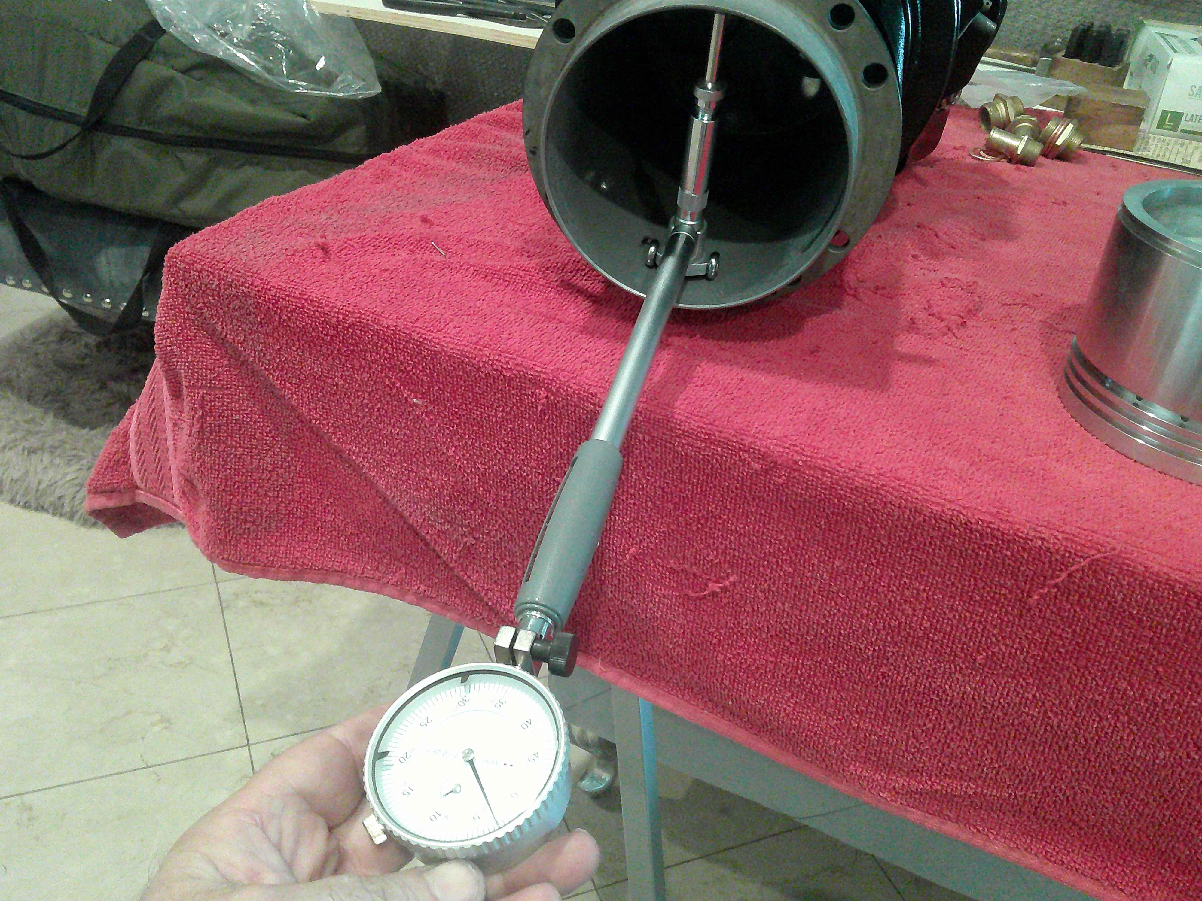
Now, even though I did not do the work, I still mic'ed everything to make sure no problems would surface later.

8.JPG


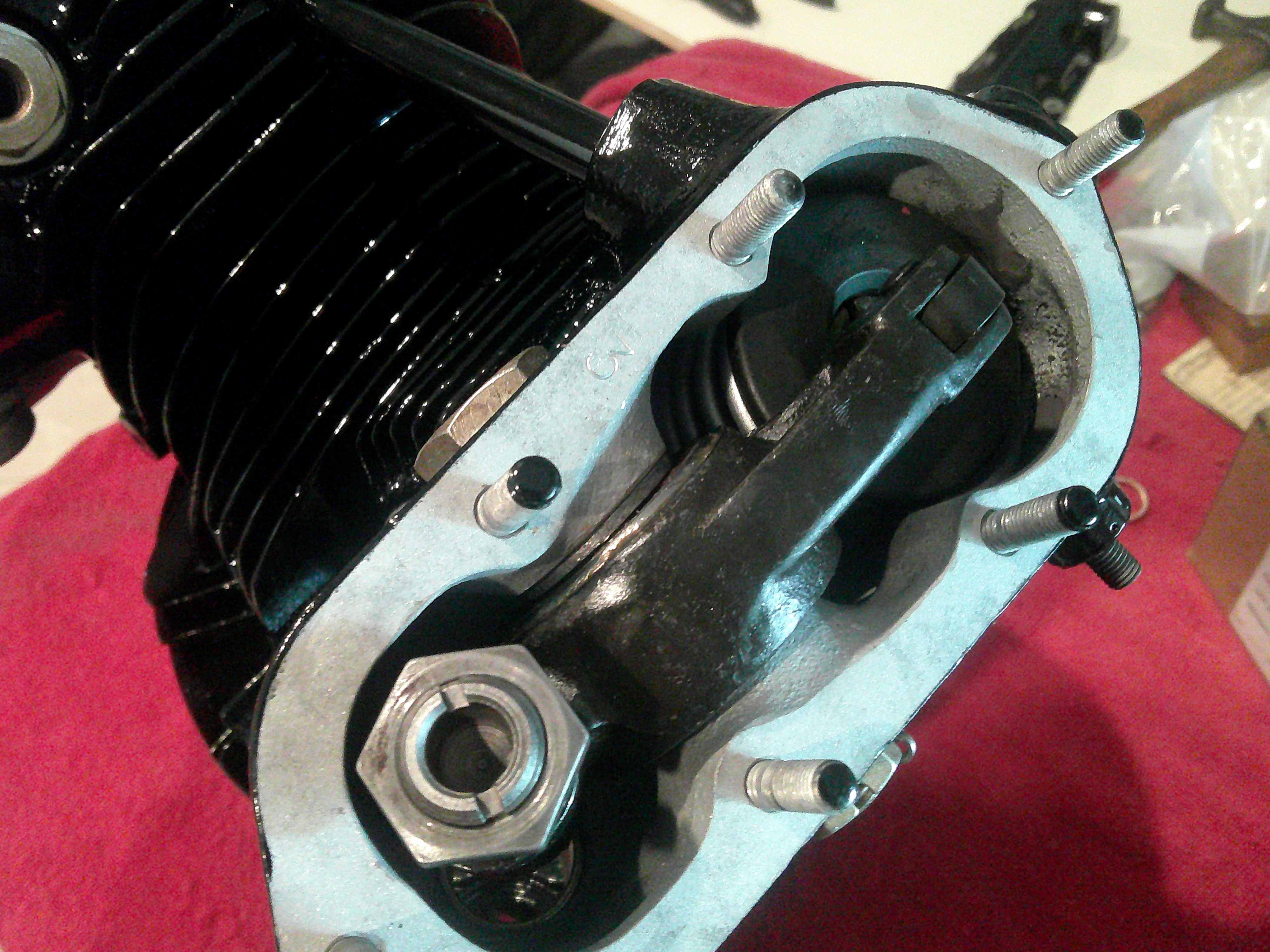
Here is a heavy-duty rocker assembly!

9.JPG


This is the best money spent...a NOS crankshaft. If you remember, the last crank was pitted, even before the previous rebuild. This one was fresh from 1940, and encased in grease. Sooo much prettier than the old one, and it has not been buried in the dirt!
91.JPG
 
There are 4 crankshaft bearings which must align within .001". This is the measurement I most feared, with an engine that augured in. It is not fatal if the measurement is out...but it does mean several weeks more work to machine out the bearing mounts and install new ones.

Anyway, the first step was to mount the accessory case on the mill table. Unfortunately, it wobbled! Years of gasket scraping had buggared the rear face, so I had to surface it back to flat again.

92.JPG
93.JPG
94.JPG


With the back face perfectly flat, I now had to build the cases on the mill table, centered on the mill spindle.

95.JPG


The point of this operation is to be able to measure the bearing bores for concentricity. This next pic is a dial gage attached to the mill spindle, so it can spin on perfect center and measure the front main roller bearing bore. The aft main bore is seen at the bottom...and it was measured next.

96.JPG


The great news is everything was within the .001" Hooyah! This was probably the only break I have had on this entire restoration!
 
With the measuring behind me, I thoroughly cleaned the cases and gave them a coat of "Continental Gold" paint.

97.JPG


In the following pic, the parts are...top left is the accessory case, which contains the gears for timing and to drive things like magnetos, oil pumps, generators and starter. Top right is the main, rear crankcase. Bottom left is the front case, holding the thrust bearing and front main bearing. On the lower right is the oil sump...tiny, as it has to fit between cylinders...but the system is "dry", so it only provides a place to collect the oil to pump out to an oil tank. The round disk is the thrust plate, which holds the thrust bearing in the front case and absorbs all the pull from the propeller, so it is not transferred to the internal engine parts. The taller small part is the oil screen. This engine did not use an oil filter...but I will retrofit a spin on filter for longevity. the last part is just a plate to cover the hole where the generator would go (my plane does not have any electrical system!?!)
98.JPG


Time for sub-assemblies. This is the master connecting rod assembly, with it's 6 articulating rods attached. I pressed knuckle pins to hold the rods to the master.

99.JPG


Here is the built up accessory case. I didn't show it, but while the case was on the mill, I removed, replaced, and bored to size the bronze bushings for all these gears. Two per gear, and I had to bore them to .001" clearance. I'd like to say it was skill. In truth...it was just programming, and the CNC did all the work!?!

For those gluttons for punishment, the gears are:

Center top (not visible under the case) is the starter gear, and the center top you can see is the the gear that is splined to the crank, providing drive for all the other gears, and taking the load from the starter gear during start too. The top, outer gears drive the magnetos. The center, double gear, drives the cam disc, which we will see later in the crankcase. The lower outer gears drove the oil pressure pump (right side), and the oil scavenge pump (left side). The lower center gear transfers through the case to drive the generator...if I had one?!

All the rounded parts of the case casting are oil passages, as every gear bushing has pressure lubrication.

991.JPG
 
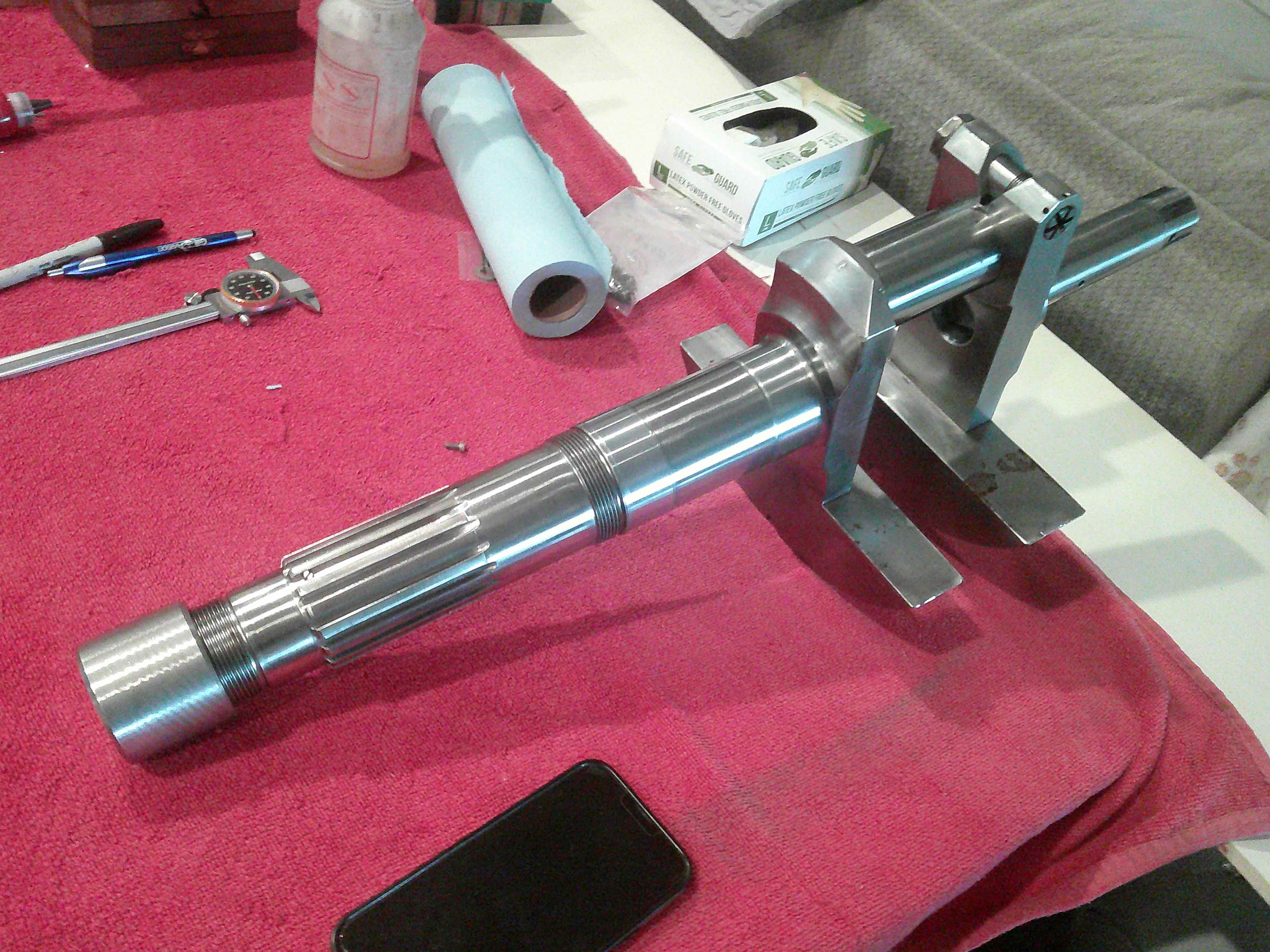
It's a new crankshaft...but there there is a catch! The rear of the shaft is removable in order to install the master rod assembly. When put back together, the shaft must still run within .001". Once the assembly is built, then it must be tested for runout. I had to undo it twice until I got the perfect alignment...a good day of work! the crank is held together with a pinch bolt, which is tightened to a stretch value instead of a torque. Just guessing, with the 48" extension I was using, I bet the torque is close to 700ftlbs.

992.JPG


Now the straight crank is installed in the front crankcase, and the nut that holds the thrust bearing is brought to 600ftlbs. Notice I have covered all the connecting rods. That prevents damage to the rods or the case until the cylinders are installed.

993.JPG


Now the sub-assemblies start going together. You may remember the rotary stand from previously. I built it from pictures in the engine manual, but made it too small...I could not get the 2 side cylinders through the frame. So last week I had to expand the stand. It works great now, and space for cylinders was not a problem for assembly.


994.JPG


This is the rear of the main crankcase. You can see the large cam disc...with 2 tracks. Of course, one track is exhaust and the other intake. you can see the roller lifters all around the cam. The very large internal gear meshes with the tall gear in the previous post to turn the cam.

The complicated part is how to time the valves...and the solution is ingenious! If you notice the center gear closely, it has serrations. These line up with serrations on the starter gear in the accessory case. So, the crank is keyed to the starter gear with the sprocket on the end. The starter gear is allowed to slide fore and aft, which engages or disengages the serrations. When disengaged, the crank turns free and the cam sits still. When the starter gear is slid forward, it engages the serrations, locking the cam gear to the starter gear. Once the timing is set, then a nut will go in the end of the crank to permanently lock the gears, so the crank drives the starter gear, and the starter gear is locked to the cam gear.

Now...if you mind is not blown yet, this next detail is guaranteed to. The cam disk turns opposite the direction of the crankshaft, and it turns at 1/6 the speed of the crank. Figure that out!!?!

If you are still holding on, the firing order is basically every other cylinder, so 1,3,5,7,2,4,6, and then starts over. So every other cylinder, and there is an odd number of cylinders. The cam has 3 lobes, spinning backwards. So the first lobe activates the #1 exhaust and intake. Then, the second lobe engages cylinder #3 exhaust and intake. Finally, the 3rd lobe actuates the #5 exhaust and intake. So all 3 lobes have independently actuated 3 cylinders. by now, moving backwards, lobe #1 has moved to cylinder #7...actuating exhaust and intake. Lobe 2 now has moved to #2 cylinder...followed by the 3rd lobe reaching cylinder #4.

One more time around, and the 3 lobes finish up cylinders 6,1, and 3...so they already start over.

If you understand this, you are better than I. It took me months to come to a mental understanding. I am still amazed at how simple, yet complex this engine is! To take it a little further, when you set the tappet clearance for the cylinders, you have to set each one 3 times. Have you figured out why, yet?? That is because each cylinder sees all 3 lobes, and the machining of the lobes can be very slightly different. You set so no lobe gives less than .010".

995.JPG
 
Now the accessory case goes onto the back of the crank case. From left to right, you see the joint oil pump and scavenge pump. In the center is the oil screen. To the right is the rocker scavenge. Since the top of the lower cylinders are much lower than the oil sump, there must be a pump to pull the oil from the rockers to the sump. Then, the main scavenge pump can take it from the sump to the oil tank, where it waits for the pressure pump to suck it back out and go through the circuit again.

The large round opening will be for the starter. The side holes are where the magnetos mount. The small center hole is the nut to hold the starter gear against the cam gear serrations....a VERY important nut! If it slips, the valve timing goes out of whack in an instant. I don't think the valves will hit the pistons (we're at only 5.6:1 compression), but the engine will not run.

Once the crank end nut is tightened, then a dual tachometer drive bolts onto the back of that crankshaft nut. One tach front seat, and one back!

Notice that every single nut and bolt has a positive lock. They are locked by cotter, safety wire, or a second jam nut called a "pal nut".

996.JPG


And finally...time to add the cylinders! this is where the engine starts to look "right" again. You MUST start at the #1 cylinder first. It has the master connecting rod. If you start anywhere else, the master rod can lay to the side and allow the other pistons to pull farther into the case than normal. If that happens, then the lower ring will spring out and lock the piston under the cylinder. Pandemonium...and, like crossing the streams, an important safety tip!

The piston goes on first. The pin slides in to hold it, and the aluminum caps at each end hold the pin in place. This is called "full floating".

997.JPG


This is where you should have a 5.25" ring compressor. I don't. I managed to rock the cylinder and push the rings together enough to slide the cylinder over them. Not the recommended way...but it worked.

998.JPG


Here you see them coming together, pal nuts and all. It is important to follow the manual explicitly, or you can get in a bind. The area at the bottom is where the sump, carb, #5 exhaust, and valve pushrods all fight for space. If you do anything in the wrong order, you may not be able to install some of the nuts!
999.JPG


This is cylinders in, but before the pushrod tubes were installed. Once the pushrods go in, space is all accounted for. Later the throttle and mixture linkages will have to go in this area too. I can't wait?!?
9991.JPG
 
Wrapping it up for this update, I timed the cam. Here is the degree wheel installed. Basically, you turn the crank until the #1 exhaust valve just starts to close. At this point, the crank could be in any random position. You then release the crankshaft bolt at the rear, which frees the cam gear from the crankshaft starter gear. Now, you turn the crank to TDC...the cam will remain at the exhaust closing point. Once the crank and cam are in sync, you connect them back up by tightening the rear crank bolt, locking the cam gear to the starter gear...for the life of the rebuild!

9992.JPG


One cool thing, the handle on my crank wrench it keyed to the crankshaft crank pin. So you can easily find TDC of any cylinder by aligning the handle with that cylinder. It's not close enough for cam or ignition timing, but it gets you very close. The degree wheel gets you spot on.

That's it for now. I thought the engine was going to be a 2 month "freshen-up", since it only had 2.6 hours on the rebuild. It turned in to a very expensive, 9 month job. But, I can now feel confident that it is rebuilt to an "as new" condition. Next on the agenda:

I have to test the magnetos. That will require building a jig to hold and spin the mags on the lathe...so I can precisely control the speed and read the output. Then they can go on and be timed to the engine. After that, there are a handful of small projects I need to complete...like straps to hold the pitot tube and vacuum horn on the struts, and to run fuel lines from the top wing, and the like. After that, the plane is ready for final assembly. It will be in the state that a Stearman would arrive at an airfield in a crate for final assembly and flight test.

Stay tuned!
 
Last edited:
Hi John, if there are no electrics how do you power beacons and strobes and if it is getting close to last light do you have to find somewhere to land before dark?
Regards Graham.
 
I used to own a Stearman, put many hours flying it, and wish to say that your work on restoring this aircraft is so beautifully done! I am so anxious to see the finished product. My compliments, sir, on such beautiful work! (y)
 
Wow !
 
Terrific work! You did a pretty good job of explaining how the valve timing works, which is saying something.
 
Thanks, guys.

Graham, it's a daytime, VFR only plane...which is fine...for now. I considered adding a radio and intercom. But that would require a battery and generator to keep it charged. Then, with a generator, the FAA mandates battery and generator cut-offs, a transponder, an ADSB, and TCAS...and...well, it gets complicated on a plane from a different era. Like the great Waldo Pepper said, "what next, highways in the sky?" For now I plan on a hand held radio and Bluetooth intercom, and let the plane fly free of modern junk.
 
Thanks, guys.

Graham, it's a daytime, VFR only plane...which is fine...for now. I considered adding a radio and intercom. But that would require a battery and generator to keep it charged. Then, with a generator, the FAA mandates battery and generator cut-offs, a transponder, an ADSB, and TCAS...and...well, it gets complicated on a plane from a different era. Like the great Waldo Pepper said, "what next, highways in the sky?" For now I plan on a hand held radio and Bluetooth intercom, and let the plane fly free of modern junk.
ELT?
 
I'm glad there is an interest. This will likely be my last large scale project...I would like to spend more time on other ventures in my "golden years". I plan to keep the projects "manageable"?!?

And yes, ELT is mandatory, even without an electrical system. It has it's own battery that must be checked at annuals.
 
Back
Top