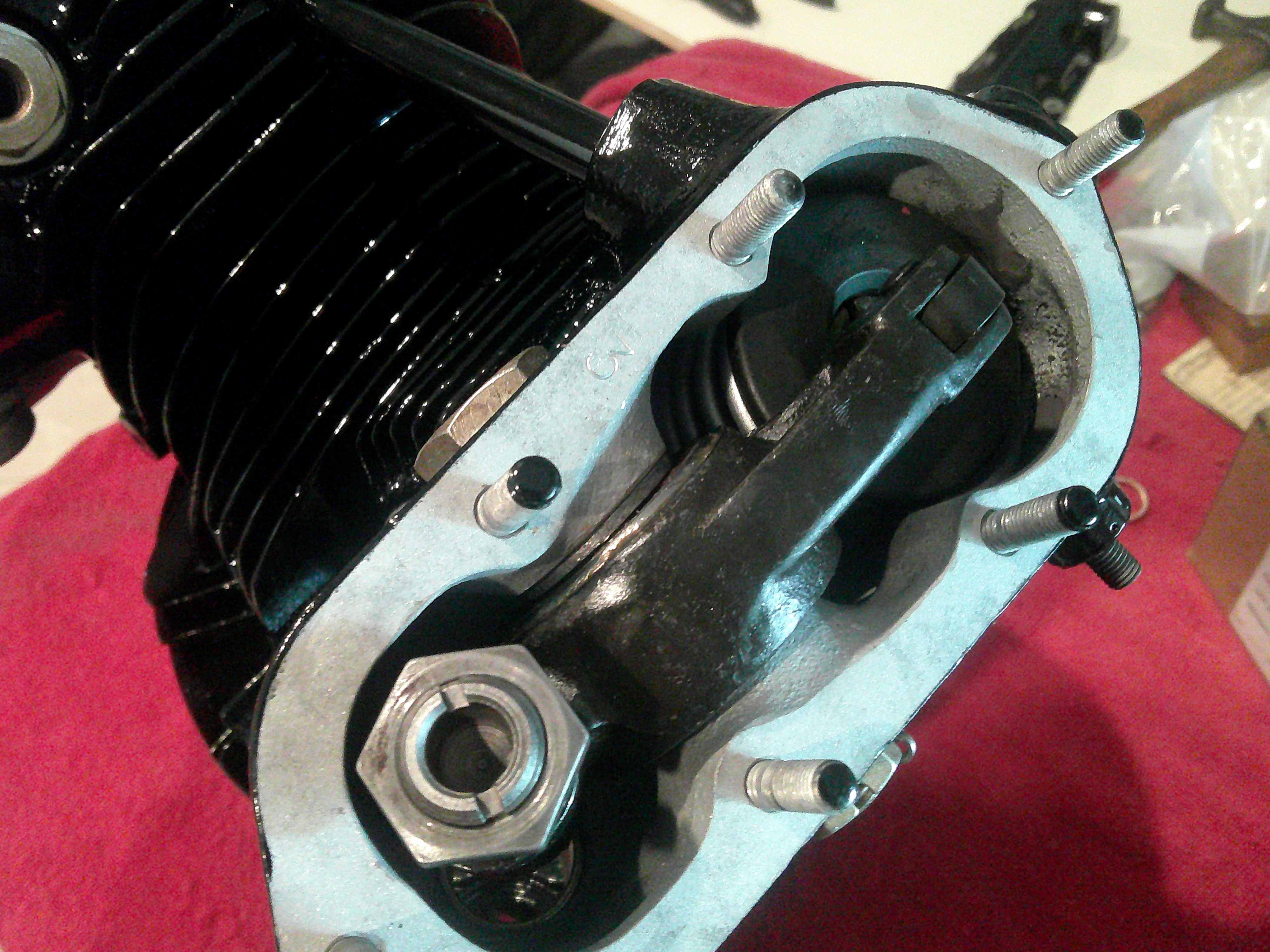
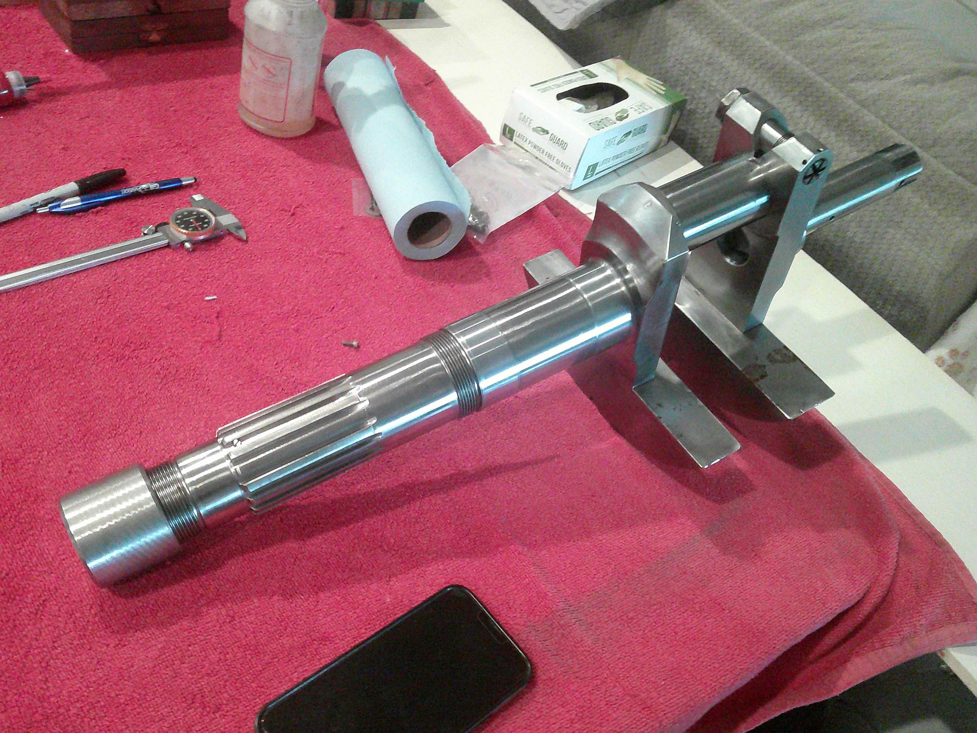
It's a new crankshaft...but there there is a catch! The rear of the shaft is removable in order to install the master rod assembly. When put back together, the shaft must still run within .001". Once the assembly is built, then it must be tested for runout. I had to undo it twice until I got the perfect alignment...a good day of work! the crank is held together with a pinch bolt, which is tightened to a stretch value instead of a torque. Just guessing, with the 48" extension I was using, I bet the torque is close to 700ftlbs.
Now the straight crank is installed in the front crankcase, and the nut that holds the thrust bearing is brought to 600ftlbs. Notice I have covered all the connecting rods. That prevents damage to the rods or the case until the cylinders are installed.
Now the sub-assemblies start going together. You may remember the rotary stand from previously. I built it from pictures in the engine manual, but made it too small...I could not get the 2 side cylinders through the frame. So last week I had to expand the stand. It works great now, and space for cylinders was not a problem for assembly.
This is the rear of the main crankcase. You can see the large cam disc...with 2 tracks. Of course, one track is exhaust and the other intake. you can see the roller lifters all around the cam. The very large internal gear meshes with the tall gear in the previous post to turn the cam.
The complicated part is how to time the valves...and the solution is ingenious! If you notice the center gear closely, it has serrations. These line up with serrations on the starter gear in the accessory case. So, the crank is keyed to the starter gear with the sprocket on the end. The starter gear is allowed to slide fore and aft, which engages or disengages the serrations. When disengaged, the crank turns free and the cam sits still. When the starter gear is slid forward, it engages the serrations, locking the cam gear to the starter gear. Once the timing is set, then a nut will go in the end of the crank to permanently lock the gears, so the crank drives the starter gear, and the starter gear is locked to the cam gear.
Now...if you mind is not blown yet, this next detail is guaranteed to. The cam disk turns opposite the direction of the crankshaft, and it turns at 1/6 the speed of the crank. Figure that out!!?!
If you are still holding on, the firing order is basically every other cylinder, so 1,3,5,7,2,4,6, and then starts over. So every other cylinder, and there is an odd number of cylinders. The cam has 3 lobes, spinning backwards. So the first lobe activates the #1 exhaust and intake. Then, the second lobe engages cylinder #3 exhaust and intake. Finally, the 3rd lobe actuates the #5 exhaust and intake. So all 3 lobes have independently actuated 3 cylinders. by now, moving backwards, lobe #1 has moved to cylinder #7...actuating exhaust and intake. Lobe 2 now has moved to #2 cylinder...followed by the 3rd lobe reaching cylinder #4.
One more time around, and the 3 lobes finish up cylinders 6,1, and 3...so they already start over.
If you understand this, you are better than I. It took me months to come to a mental understanding. I am still amazed at how simple, yet complex this engine is! To take it a little further, when you set the tappet clearance for the cylinders, you have to set each one 3 times. Have you figured out why, yet?? That is because each cylinder sees all 3 lobes, and the machining of the lobes can be very slightly different. You set so no lobe gives less than .010".


 Hey Guest!