
-
 Hey Guest!
British Car Forum has been supporting enthusiasts for over 25 years by providing a great place to share our love for British cars. You can support our efforts by upgrading your membership for less than the dues of most car clubs. There are some perks with a member upgrade!**Upgrade Now**
(PS: Upgraded members don't see this banner, nor will you see the Google ads that appear on the site.)
You are using an out of date browser. It may not display this or other websites correctly.
You should upgrade or use an alternative browser.
You should upgrade or use an alternative browser.
General TR Instrument Faces
- Thread starter CJD
- Start date


HerronScott
Darth Vader
Offline
What part numbers are you looking for? These are some of the valid ones for the KPH speedometers based on information from Limora and Moss Europe.
S628K 3.7:1 740?
SN6307/05 3.7:1 740? (maybe 737)
SN6307/09 4.1:1 820?
SN6319/01 3.7:1 740?
SN6319/03 4.1:1 820?
Scott
S628K 3.7:1 740?
SN6307/05 3.7:1 740? (maybe 737)
SN6307/09 4.1:1 820?
SN6319/01 3.7:1 740?
SN6319/03 4.1:1 820?
Scott
TexasKnucklehead
Jedi Knight
Offline
I thought this was a great forum, with some wonderful people.... But when Jesus comes here asking for help, and gets it, you have to know this is a good place.
Hi John,
You seem to walk always some steps ahead of me..., and now you come up with the complete drawing of the KMH face. Great!
As told you by emal, I am trying to get the information about the right codes for the speedo face. It seems that for the standard rear axle ratio of 3.7:1, the turns per kilometer should be 740. The part number must be one of those posted by Scott:
S628K or SN6307/05 or SN6319/02
Anybody knows the differences between them?
Jesús
OP
CJD
Yoda
Offline
I came up with the "733" by applying the km conversion factor to the "1180" for miles. That was a guess, so I'll switch it to 740. We are flexible on the serial number until we are ready to paint...and I'm still waiting to hear from Marv about getting a couple trashed speedos to play with. It's all coming together, though.
I haven't gotten a chance to respond to the email, but it sounds like the gears you found will be very close. I don't think the odometers on many cars are close to perfect anyway.
Cheers!
I haven't gotten a chance to respond to the email, but it sounds like the gears you found will be very close. I don't think the odometers on many cars are close to perfect anyway.
Cheers!
Hi John,
You are right: the value of 733 is the exact required. However, in those Jaeger/Smiths speedos, the actual value of turns per mile or per kilometer must be either multiple of 2 or 5 since the worm gears can have 20, 25 or 32 teeth.
The usual 1180 odometer in miles uses a 20 teeth worm gear and a 59 teeth odometer wheel. I will change the odoemter gear for one with 32 teeth: 20 x 36 = 720 (I would need a 37 teeh gear for more accuracy and reach the 740 figure).
Jesus
TR3driver
Great Pumpkin - R.I.P
Offline
There were quite a few different speedometers fitted, depending on things like which tires were fitted by the factory and which commission number. I can't find the "kph" numbers at the moment, but for example one source gives
3.7 axle, Dunlop tires SN6319/00 1184 tpm
3.7 axle, Michelin-X tires SN6319/06 1216 tpm
4.1 axle, Dunlop tires SN6319/02 1312 tpm
4.1 axle, Michelin-X tires SN6319/04 1344 tpm
I believe these would have been after TS60000, not sure about earlier cars.
If I manage to find the kph numbers, I'll post them here.
HerronScott
Darth Vader
Offline
As told you by emal, I am trying to get the information about the right codes for the speedo face. It seems that for the standard rear axle ratio of 3.7:1, the turns per kilometer should be 740. The part number must be one of those posted by Scott:
S628K or SN6307/05 or SN6319/02
Anybody knows the differences between them?
Jesús,
My guess is that they were slightly different models used during the run of the TR2-TR3B's but I haven't seen any detailed information on when the changes might have occurred.
As Randall indicated, we have information on even more models for the MPH speedometers which included different part numbers within both the SN6307/xx and SN6319/xx range for the different tire types to account for the different rolling diameters plus the different differential ratios. You would have expected the same for the KPH speedometers as well, but I haven't seen any information online to document the different models. Hopefully, Randall can come up with that information.
Here's the information I've found online for the MPH speedometers for comparison.
[TABLE="width: 436"]
[TR]
[TD]TR2-3 (Limora)
[/TD]
[TD][/TD]
[TD][/TD]
[TD][/TD]
[/TR]
[TR]
[TD]Part #
[/TD]
[TD]Mfg #
[/TD]
[TD]Spec. Code
[/TD]
[TD][/TD]
[/TR]
[TR]
[TD]S 628 51 118 504 04
[/TD]
[TD][/TD]
[TD]3.7:1
[/TD]
[TD][/TD]
[/TR]
[TR]
[TD][/TD]
[TD][/TD]
[TD][/TD]
[TD][/TD]
[/TR]
[TR]
[TD]SN 6307/04
[/TD]
[TD="align: right"]108192
[/TD]
[TD]3.7:1
[/TD]
[TD][/TD]
[/TR]
[TR]
[TD]SN 6307/11
[/TD]
[TD][/TD]
[TD]3.7:1
[/TD]
[TD]Optional Michelin X tyres
[/TD]
[/TR]
[TR]
[TD]SN 6307/08
[/TD]
[TD="align: right"]113637
[/TD]
[TD]4.1:1
[/TD]
[TD][/TD]
[/TR]
[TR]
[TD]SN 6307/10
[/TD]
[TD][/TD]
[TD]4.1:1
[/TD]
[TD]Optional Michelin X tyres
[/TD]
[/TR]
[TR]
[TD][/TD]
[TD][/TD]
[TD][/TD]
[TD][/TD]
[/TR]
[TR]
[TD]SN 6319/00
[/TD]
[TD]108192?
[/TD]
[TD]3.7:1
[/TD]
[TD][/TD]
[/TR]
[TR]
[TD]SN 6319/06
[/TD]
[TD]119047?
[/TD]
[TD]3.7:1
[/TD]
[TD]Optional Michelin X tyres
[/TD]
[/TR]
[TR]
[TD]SN 6319/02
[/TD]
[TD]113632?
[/TD]
[TD]4.1:1
[/TD]
[TD][/TD]
[/TR]
[TR]
[TD]SN 6319/04
[/TD]
[TD="align: right"]119046
[/TD]
[TD]4.1:1
[/TD]
[TD]Optional Michelin X tyres
[/TD]
[/TR]
[/TABLE]
Scott
TR3driver
Great Pumpkin - R.I.P
Offline
Here are some kph numbers I found. Hopefully I can get the columns to line up. The revs/km numbers look suspicious to me, they should be different between the two sizes of tires, but maybe this will help as a starting point for further research.
Code:
[FONT=courier new][B]
    Axle    Original  Triumph part    Jaeger part   Revs/km
    ratio   tires
     3.7    5.50/5.90  108193          [FONT=courier new][B]SN6319[/B][/FONT]/01    740
     4.1    5.90       113632          [FONT=courier new][B]SN6319[/B][/FONT]/02    820
     4.1    155X       120206          [FONT=courier new][B]SN6319[/B][/FONT]/05    820
3.7 155X 120205 [FONT=courier new][B]SN6319[/B][/FONT]/07 740 [/B][/FONT]Scott and Randall, thank you for the information.
I agree, Randall: it is curios why they gave different part numbers to speedos with apparently identical face and identical odometer calibration.
Maybe they changed some other feature (materials, illumination ...).
Regards.
Jesús
I agree, Randall: it is curios why they gave different part numbers to speedos with apparently identical face and identical odometer calibration.
Maybe they changed some other feature (materials, illumination ...).
Regards.
Jesús
OP
CJD
Yoda
Offline
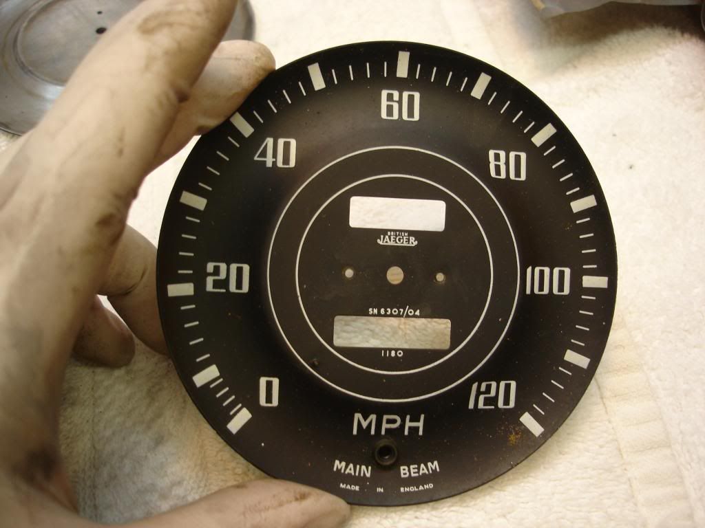
Again, thanks Randall and Scott. Jesus picked the SN he wants. This picture shows how the TR3 serials were marked:
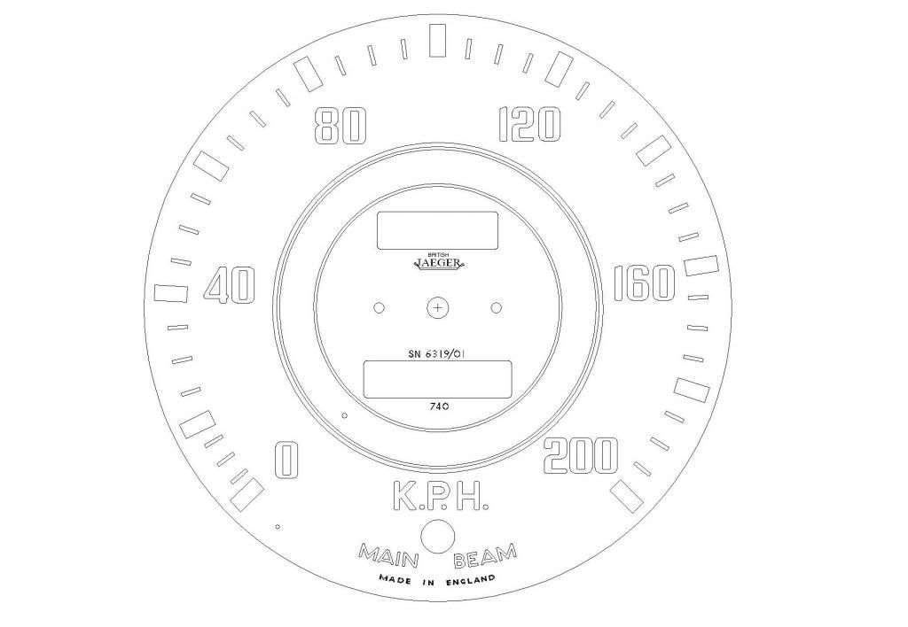
And this is the final KPH speedo, as it will look.
I still can't believe you guys came up with the numbers so fast! Anyway, now I just need to find a face to convert.
Marv...You out there?
Thanks again,
John

And this is the final KPH speedo, as it will look.

I still can't believe you guys came up with the numbers so fast! Anyway, now I just need to find a face to convert.
Marv...You out there?
Thanks again,
John
OP
CJD
Yoda
Offline
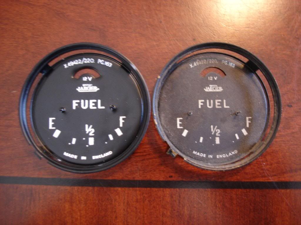
While I wait for parts on the KPH project, I'm moving on to the small gages. First up is the fuel gage. The face has been a bit of a pain. The small gages are made .008" brass stampings. The problem with these is that you absolutely cannot bead blast them like I did the speedo and tach. The brass curls right up. When you straighten it, it "oil cans". If you hammer it...it dents. I then had to resort to PDR, or paintless dent removal, techniques to get a reasonably flat faced blank to work with. Save yourself the pain by simply avoiding any type of blasting. So, here is the gouge on refinishing the small faces:
1) Chemically strip the old face in thinner or other solvent.
2) Roughen the brass once it's bare with 400 grit sand paper...gently! This is merely to ensure you do not have the base paint lift later.
3) Option 2 is to roughen the original face paint, and paint right over the old with your black base color.
4) Be gentle on the needle stop pins. I do not know how they crimped those in, but once they are loose, the pin is too weak to re-crimp, and heat will warp the thin brass face. If they do loosen, a dot of super glue on the back of the face will tighten them right back up.
I'll post the face work later. For the mechanical details, I cannot do a better job than the MG Guru did:
https://mgaguru.com/mgtech/electric/fg_01.htm
The only thing I can add is that the wires you are dealing with are smaller than hairs. They re-solder easily, but save yourself the trouble by being very, very, gentle! Be sure you need to re-calibrate before you loosen anything around the 2 coils. If it's close, live with it. The movement of the coils makes absolutely no in sense how the needle reacts...so once you start you are in for hours of fiddling until you get it right...and that will be by accident.
And that's all I plan to add about the fuel gage mechanicals!
OP
CJD
Yoda
Offline
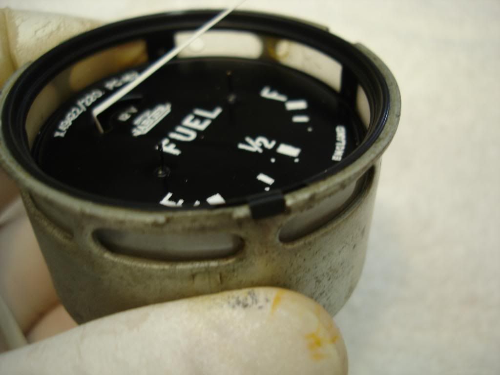
This is the pictorial of the fuel gage face. I started pretty cocky after completing the speedo and tach. I thought the small, flat faces would be a piece of cake. Unfortunately, my learning curve was not over. I had to refinish the fuel face 5 times before I was satisfied. The issue was that when I pealed the masking vinyl...some of the numbers would peal right off with the mask.
Bummer.
I ran a dozen tests on the pizza tins, and finally discovered what the problem was. I was using semi gloss white and pealing it to soon. The surface was flashing, but the under layer was still wet. The surface flash was bringing the whole white coat up with it as a sheet. This "flash" problem was accentuated by the fact the markings on the fuel gage are smaller than those on the tach/speedo. The paint wanted to remain as a sheet, instead of breaking and leaving my markings behind. The solution was pretty simple. I switched to flat white, which has a less thick surface flash by its nature. And, I let the white dry for a couple hours before pealing. All was good...and I will start the last 3 gages much more humble!
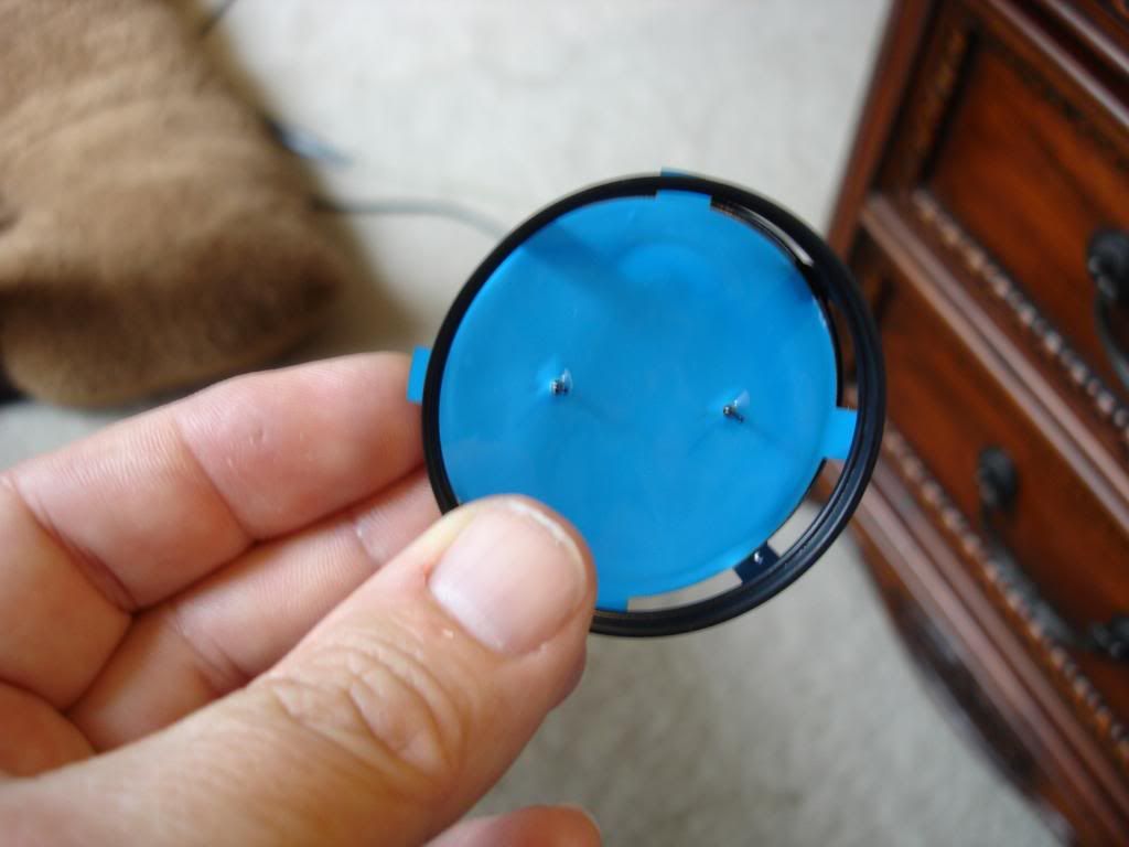
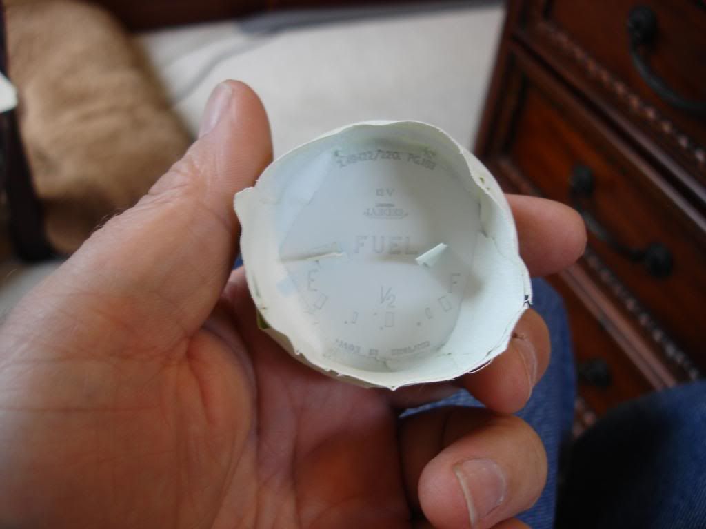
This is the blank face. If you look closely, you will notice the slight waviness. This is as good as I could massage the thin metal after making the mistake of bead blasting it. For those who follow...don't bead blast! The waves will be optically broken once the markings are on, so it will not be noticeable (I hope!?!)
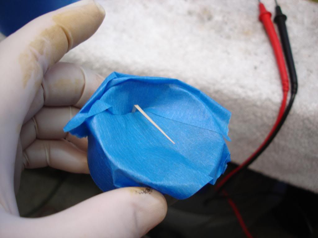
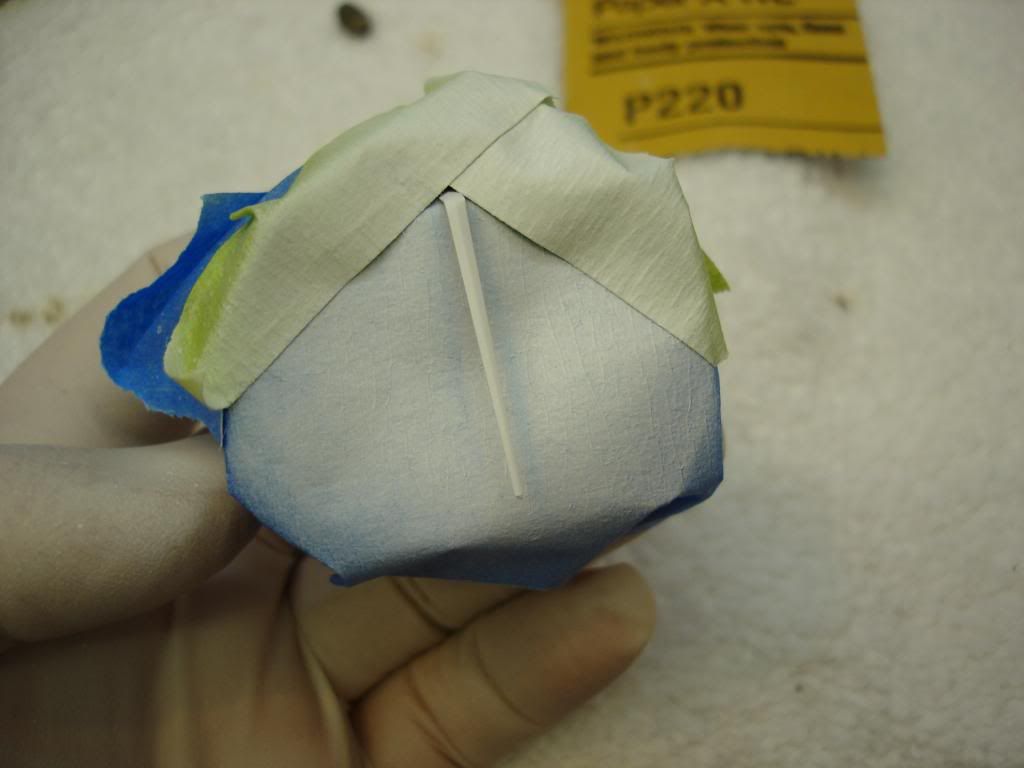
The tach/speedo were just wrapped with the vinyl. The small gages have a rim, which poses a special challenge. I had to pre-cut the mask to fit down within the rim:
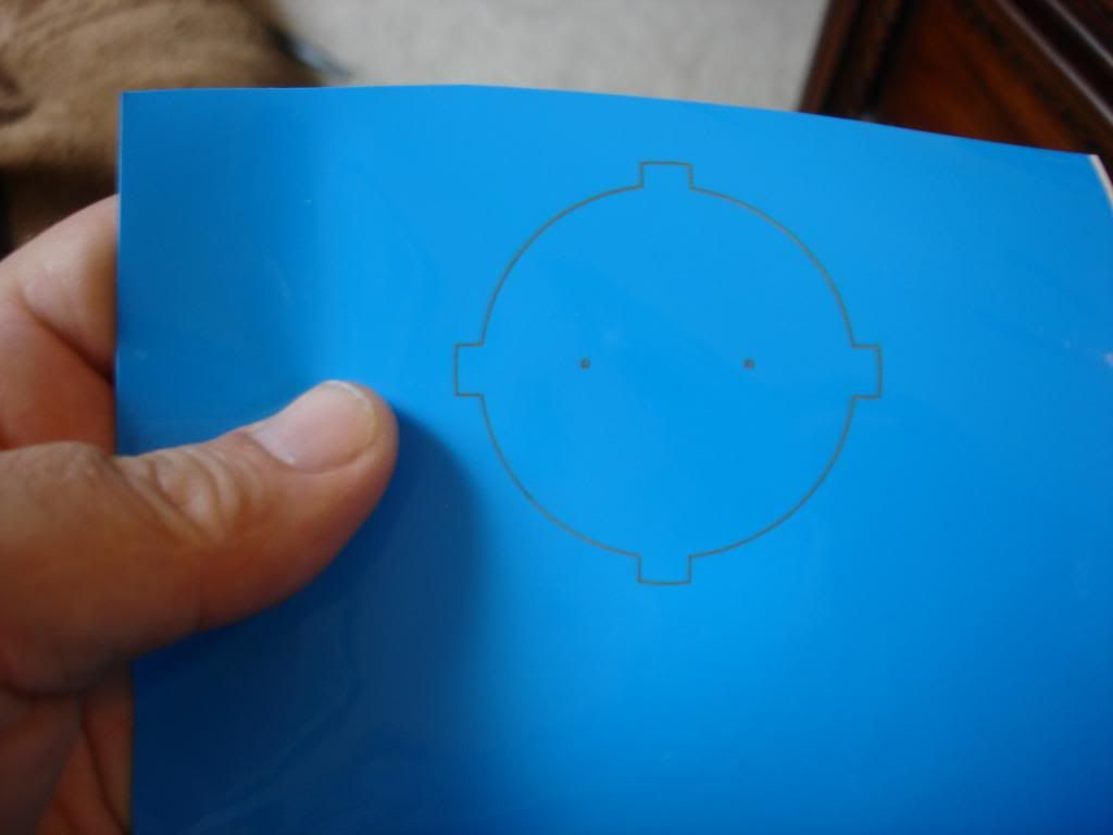
After the first attempt, I learned to add the small tabs to help peal the mask back. It was a bear without it. Now time for the laser to do its thing...
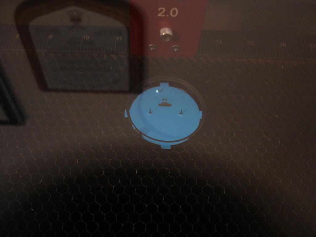
This is my first try (out of 5 I'm sad to say). Notice I forgot to cover the small needle stops.
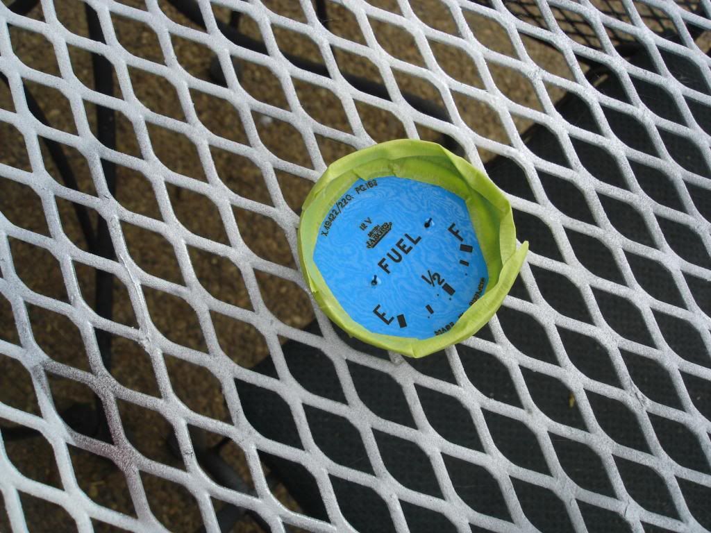
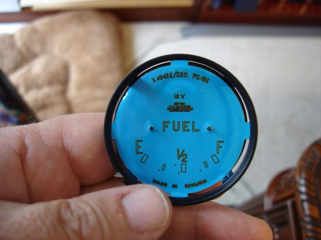
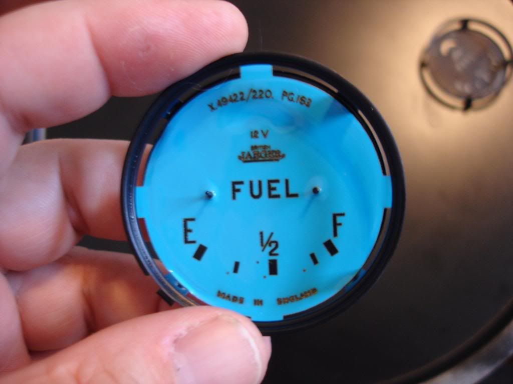
By attempt 5, I remembered the pins. All told, between the test runs and failed tries, a dozen is a charm.
Bummer.
I ran a dozen tests on the pizza tins, and finally discovered what the problem was. I was using semi gloss white and pealing it to soon. The surface was flashing, but the under layer was still wet. The surface flash was bringing the whole white coat up with it as a sheet. This "flash" problem was accentuated by the fact the markings on the fuel gage are smaller than those on the tach/speedo. The paint wanted to remain as a sheet, instead of breaking and leaving my markings behind. The solution was pretty simple. I switched to flat white, which has a less thick surface flash by its nature. And, I let the white dry for a couple hours before pealing. All was good...and I will start the last 3 gages much more humble!
This is the blank face. If you look closely, you will notice the slight waviness. This is as good as I could massage the thin metal after making the mistake of bead blasting it. For those who follow...don't bead blast! The waves will be optically broken once the markings are on, so it will not be noticeable (I hope!?!)

The tach/speedo were just wrapped with the vinyl. The small gages have a rim, which poses a special challenge. I had to pre-cut the mask to fit down within the rim:


After the first attempt, I learned to add the small tabs to help peal the mask back. It was a bear without it. Now time for the laser to do its thing...


This is my first try (out of 5 I'm sad to say). Notice I forgot to cover the small needle stops.

By attempt 5, I remembered the pins. All told, between the test runs and failed tries, a dozen is a charm.


OP
CJD
Yoda
Offline
I finished the little gages. This will be my last installment on "how to" with gages...
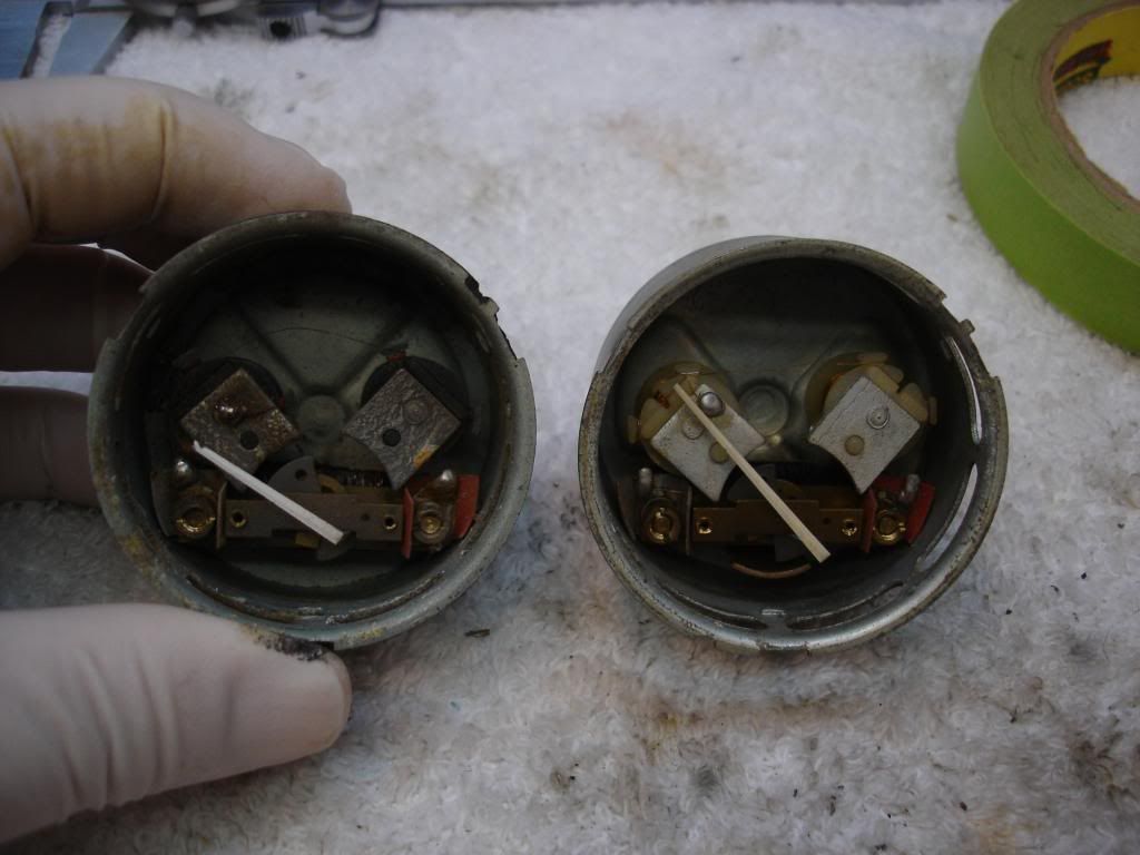
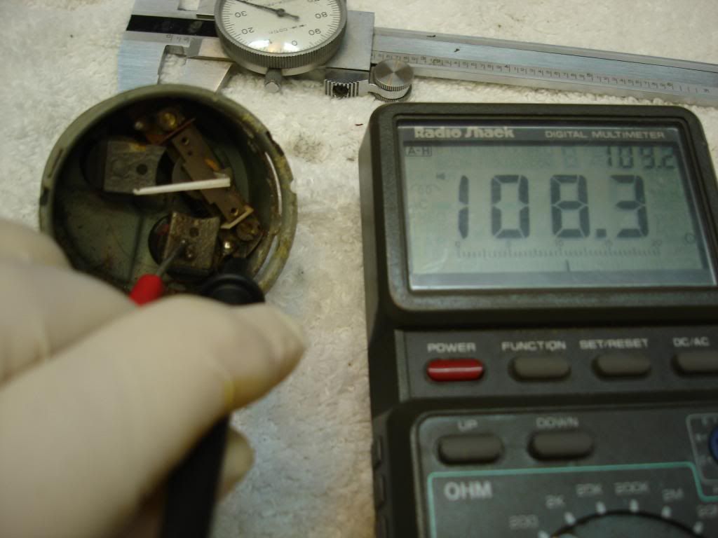
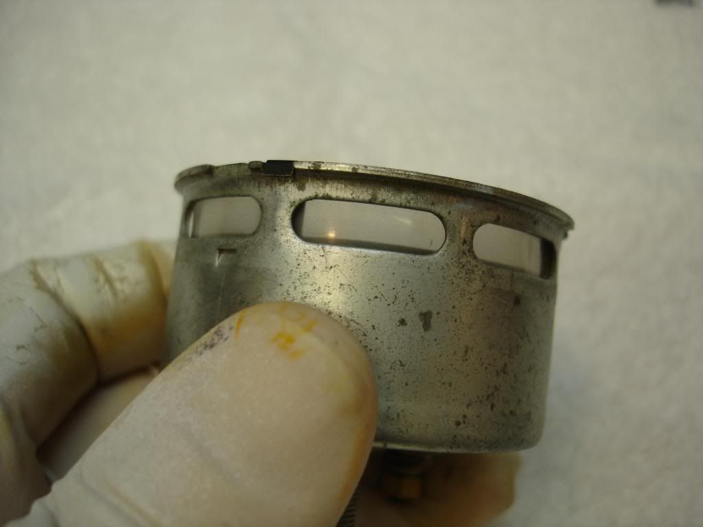
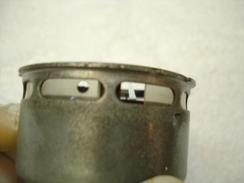
These are the 2 fuel gages I have. The one on the left was so bad the tip of the needle corroded off. But it still works! Before putting a lick on time into either, I checked the continuity of the coils using an ohm meter. This is the right coil. It should be around 100 ohms, give or take.
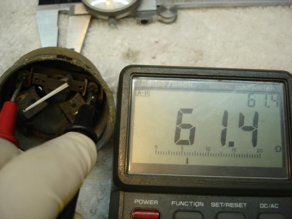
And this is the left coil and resistor together. 60 ohms here is correct, give or take. If the reading is 100 or more, then one is open.
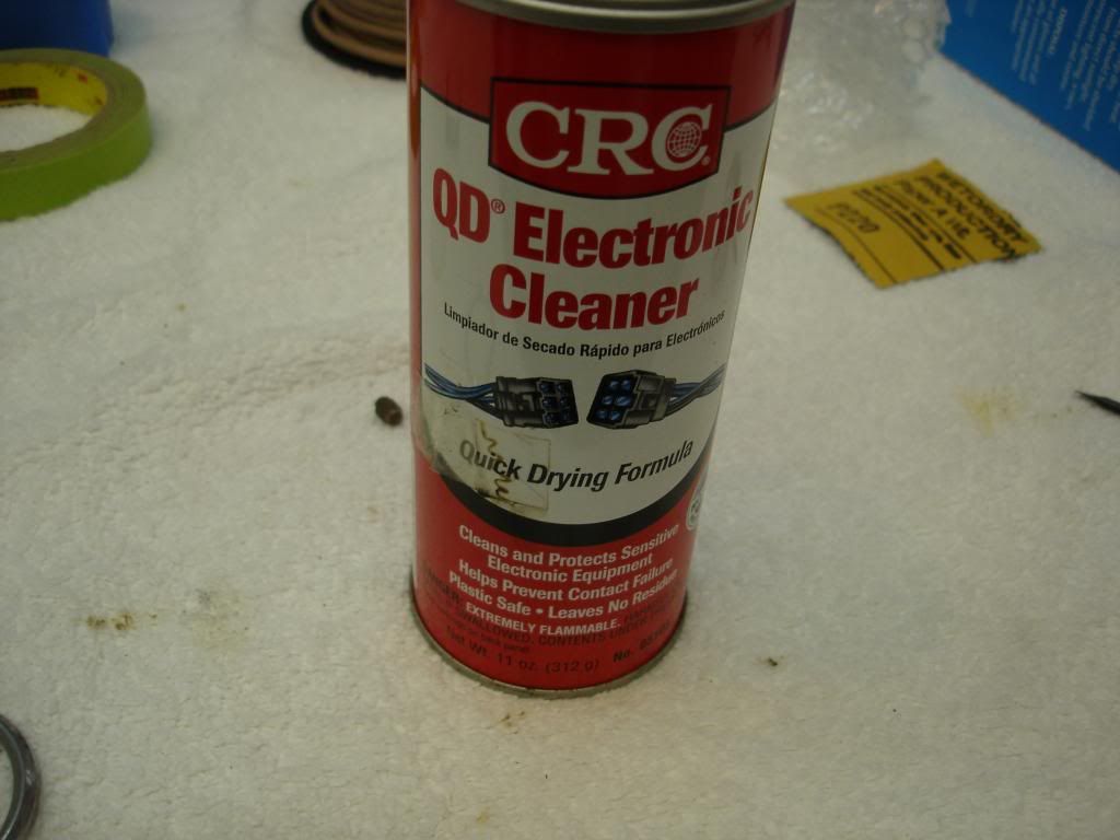
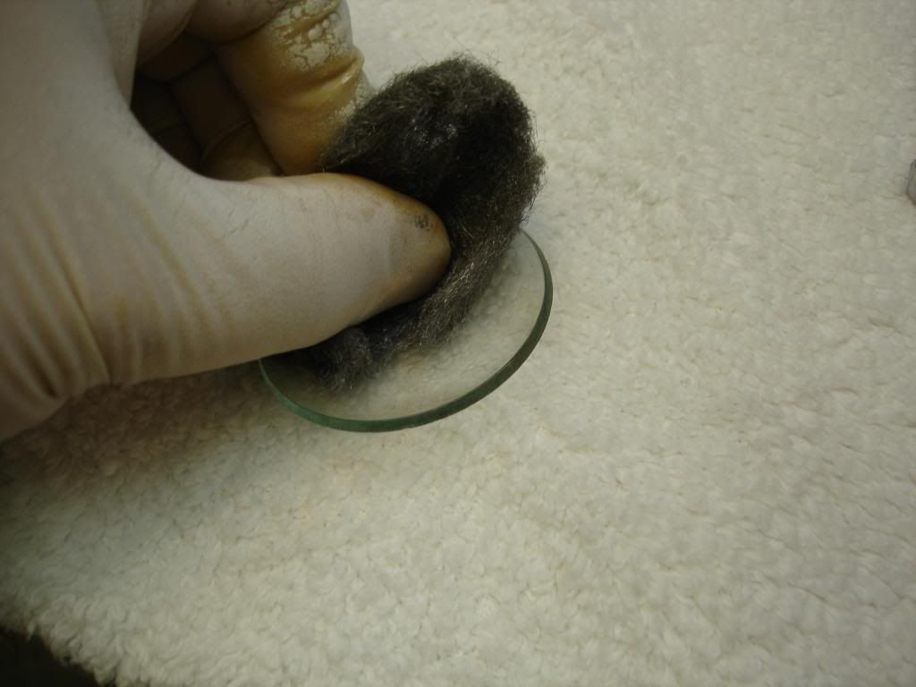
I decided to keep the gage on the right. First, I cleaned the gage inside, and bead blasted the outside. The tiny wires are merely coated in laquer for instulation, so no harsh cleaners, like carb or brake cleaners. Here is what I recommend:
Now to paint the needle. I used the same Krylon flat white as the faces.
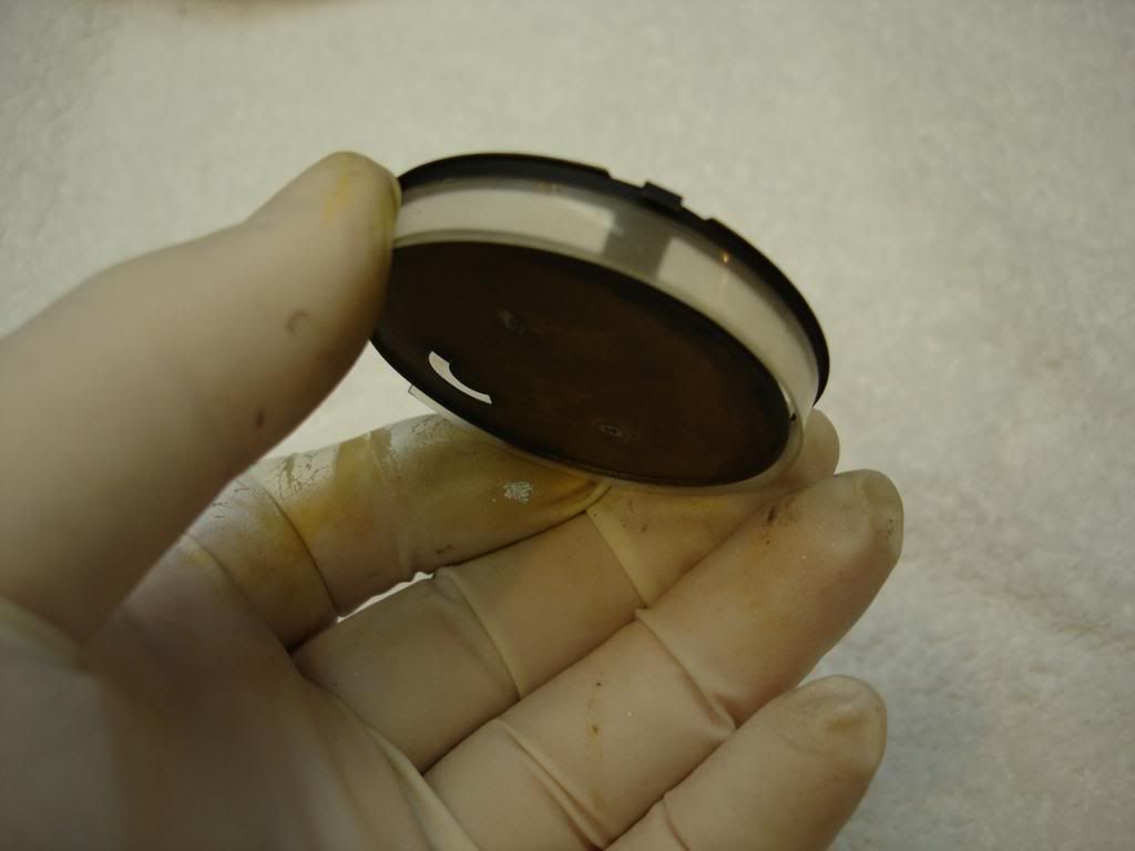
This is the clear plastic "window" that lets the light from the external bulb into the instrument. It must be clean and clear to work. Ensure it fits properly around the face. It is not complicated, so you can fashion one from any clear platic sheet if yours is broken.
'

These are the 2 fuel gages I have. The one on the left was so bad the tip of the needle corroded off. But it still works! Before putting a lick on time into either, I checked the continuity of the coils using an ohm meter. This is the right coil. It should be around 100 ohms, give or take.

And this is the left coil and resistor together. 60 ohms here is correct, give or take. If the reading is 100 or more, then one is open.

I decided to keep the gage on the right. First, I cleaned the gage inside, and bead blasted the outside. The tiny wires are merely coated in laquer for instulation, so no harsh cleaners, like carb or brake cleaners. Here is what I recommend:

Now to paint the needle. I used the same Krylon flat white as the faces.

This is the clear plastic "window" that lets the light from the external bulb into the instrument. It must be clean and clear to work. Ensure it fits properly around the face. It is not complicated, so you can fashion one from any clear platic sheet if yours is broken.
'


OP
CJD
Yoda
Offline
I started the fuel gage first, because I knew it is the biggest pain to deal with...mainly from calibrating. If you read the write up on the link above, you see how complicated the "calibrator" can be. I will show you how simple it can be...
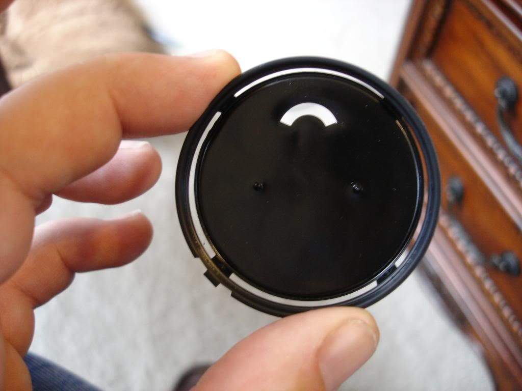
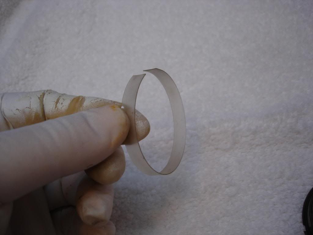
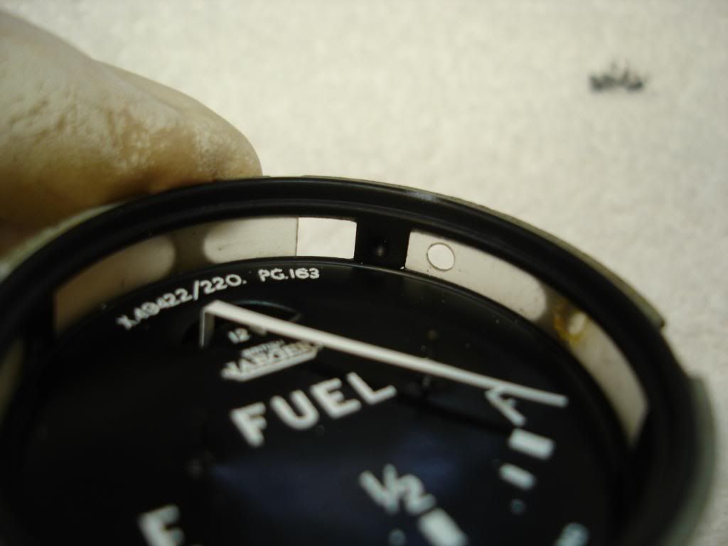
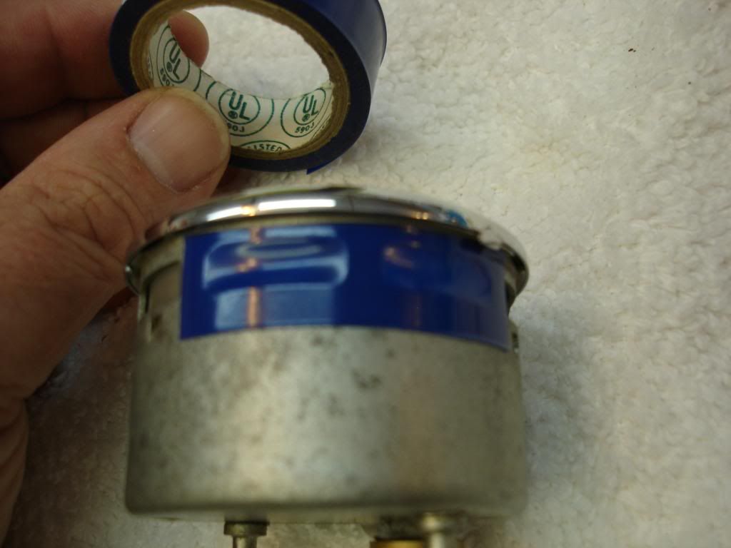
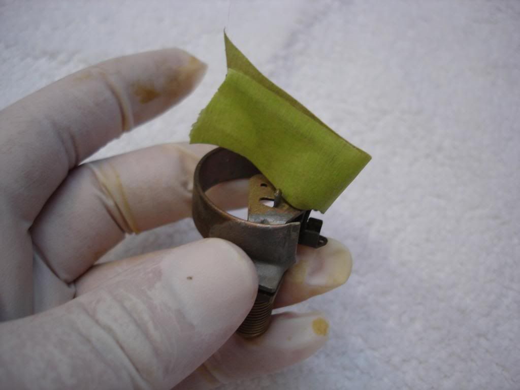
Start by mounting the gage face, with light ring:
Notice that the factory light ring has a gap. I think it shrinks over time. I place this gap on the side that will be opposite the dash light bulb, so I can seal it with vinyl tape...to keep out a bit of the enevitable dust.
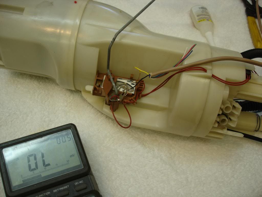
This pic is a fuel sender from a Range Rover I have laying around. I marked the float arm to show 70 ohms (full tank), 0 ohms (empty tank), and the 1/4's in between. That's all I used!
I will not go into detail about the calibrating, since it has already been done. Just a few tips, though:
1) The "E" side is best set by bending the needle to line up when the input from the sender is 0 ohm. This is because there really is no adjustment for the "E" needle position.
2) The "F" adjustment is mostly done using the "F" side coil adjustment. It is so sensitive that just starting to tighten or loosen the nut is enough to make a 1/4 indication difference.
3) The "E" side coil adjustment is primarily for the mid range fine tuning. Same here...very sensitive!!
4) never loosen the adjusting nuts more than one turn! This will allow the alignment tab for the coil to come out of the slot...and then the wires will break when you try to tighten the nut!!
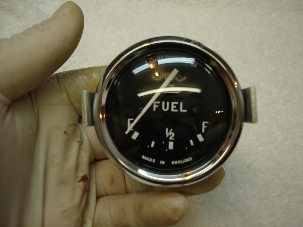
Now the final assembly:
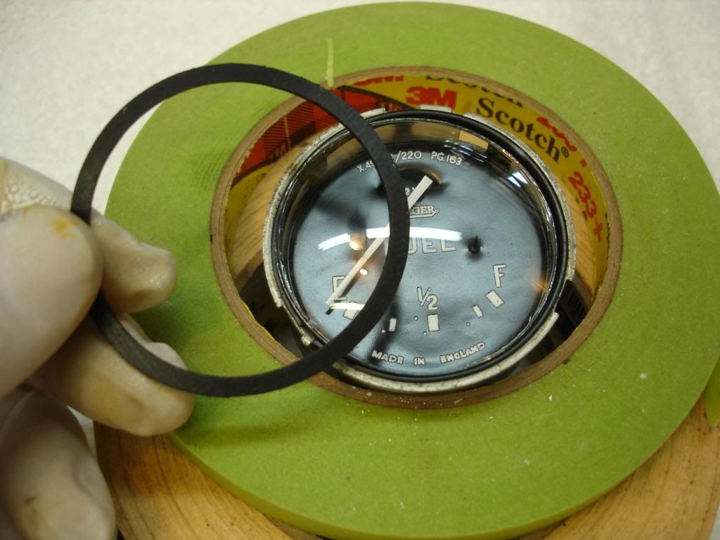
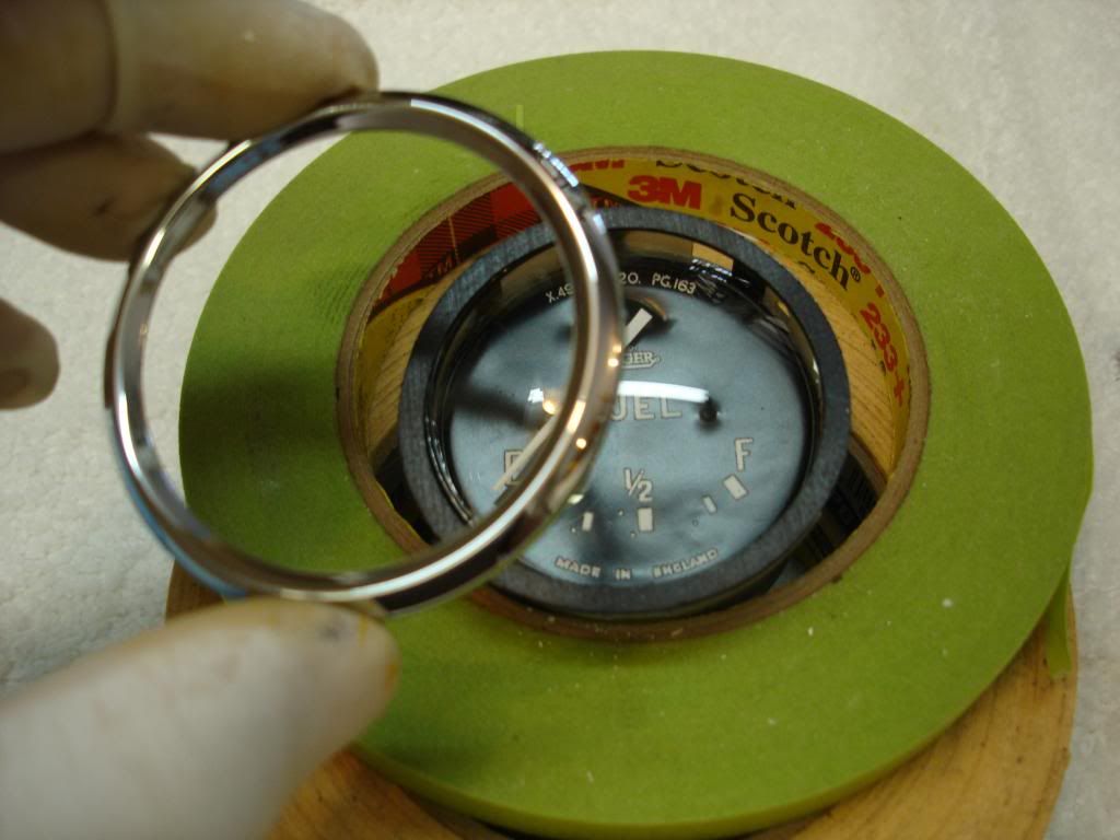
Start by mounting the gage face, with light ring:


Notice that the factory light ring has a gap. I think it shrinks over time. I place this gap on the side that will be opposite the dash light bulb, so I can seal it with vinyl tape...to keep out a bit of the enevitable dust.


This pic is a fuel sender from a Range Rover I have laying around. I marked the float arm to show 70 ohms (full tank), 0 ohms (empty tank), and the 1/4's in between. That's all I used!
I will not go into detail about the calibrating, since it has already been done. Just a few tips, though:
1) The "E" side is best set by bending the needle to line up when the input from the sender is 0 ohm. This is because there really is no adjustment for the "E" needle position.
2) The "F" adjustment is mostly done using the "F" side coil adjustment. It is so sensitive that just starting to tighten or loosen the nut is enough to make a 1/4 indication difference.
3) The "E" side coil adjustment is primarily for the mid range fine tuning. Same here...very sensitive!!
4) never loosen the adjusting nuts more than one turn! This will allow the alignment tab for the coil to come out of the slot...and then the wires will break when you try to tighten the nut!!
Now the final assembly:


OP
CJD
Yoda
Offline
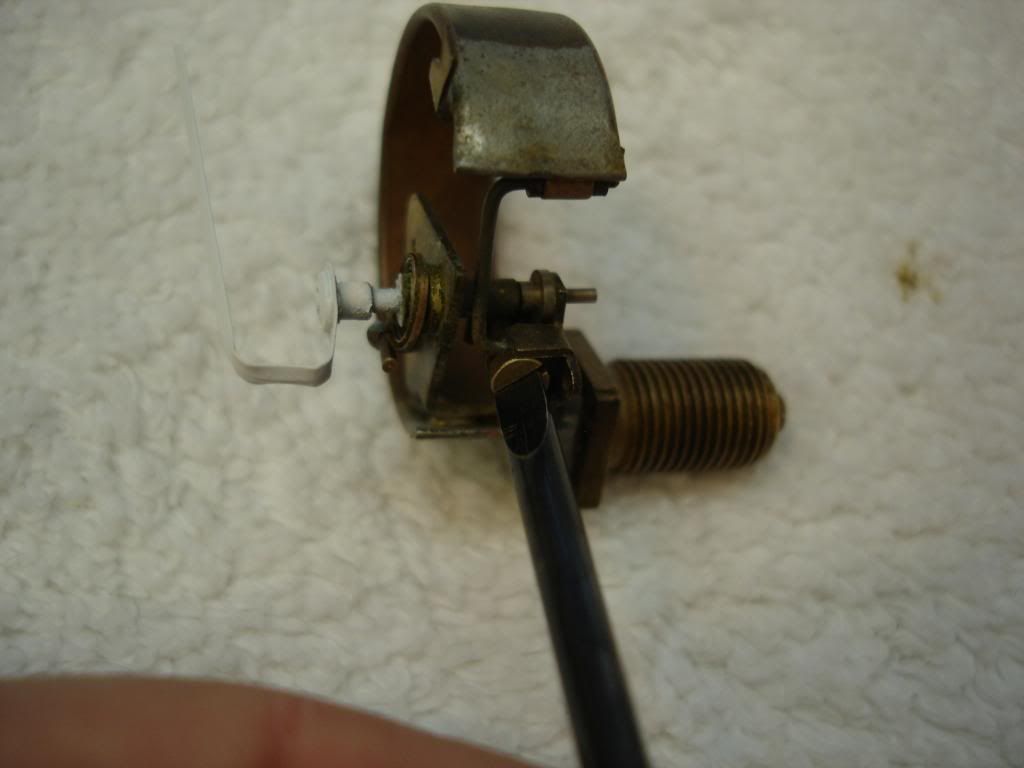
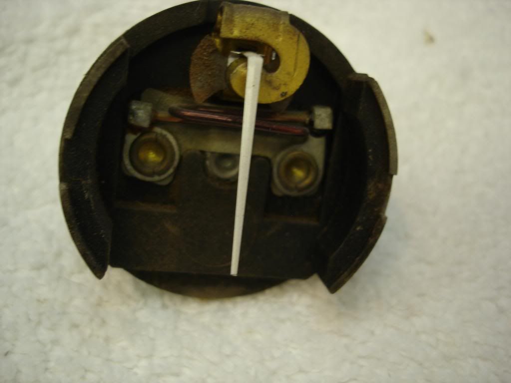
Next up, the oil . This is an entirely mechanical gage. Here is how the inside looks:
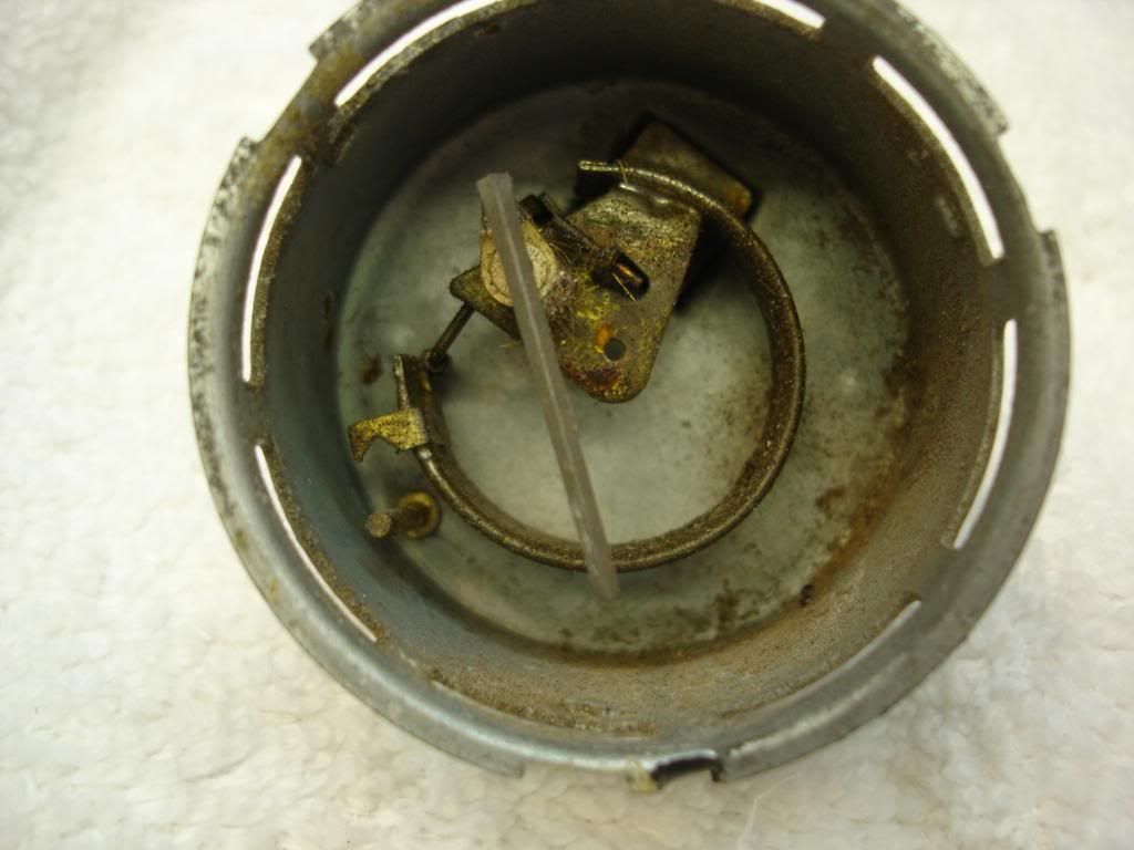
It is super simple. The rounded gland is hollow. As oil pressure is allowed inside the gland, it tried to unwind and straighten out. The motion form this unwinding is transfered to the needle by a wire soldered to the gland. That's it!
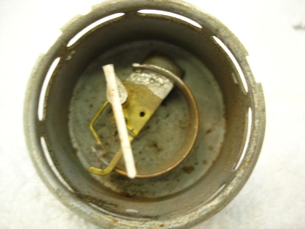
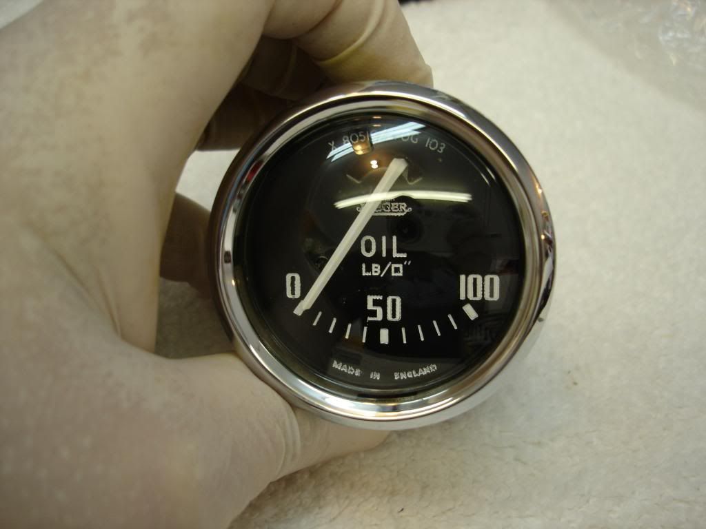
This is a newer version of the gage. It has a few different details, but it is still exactly the same mechanism:
I removed the nut holding the mechanism in the case and bead blasted everything.

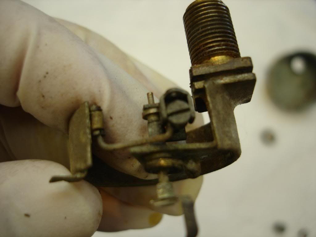
The earlier gage has an adjustment for sensitivity. You bend the wire to calibrate, but this screw is used to control the range of the needle.
And of course...there is a clock spring. The spring takes up the "slack" in the mechanism, so any play is takne up. Use care with it...
I taped the needle and spring before blasting.
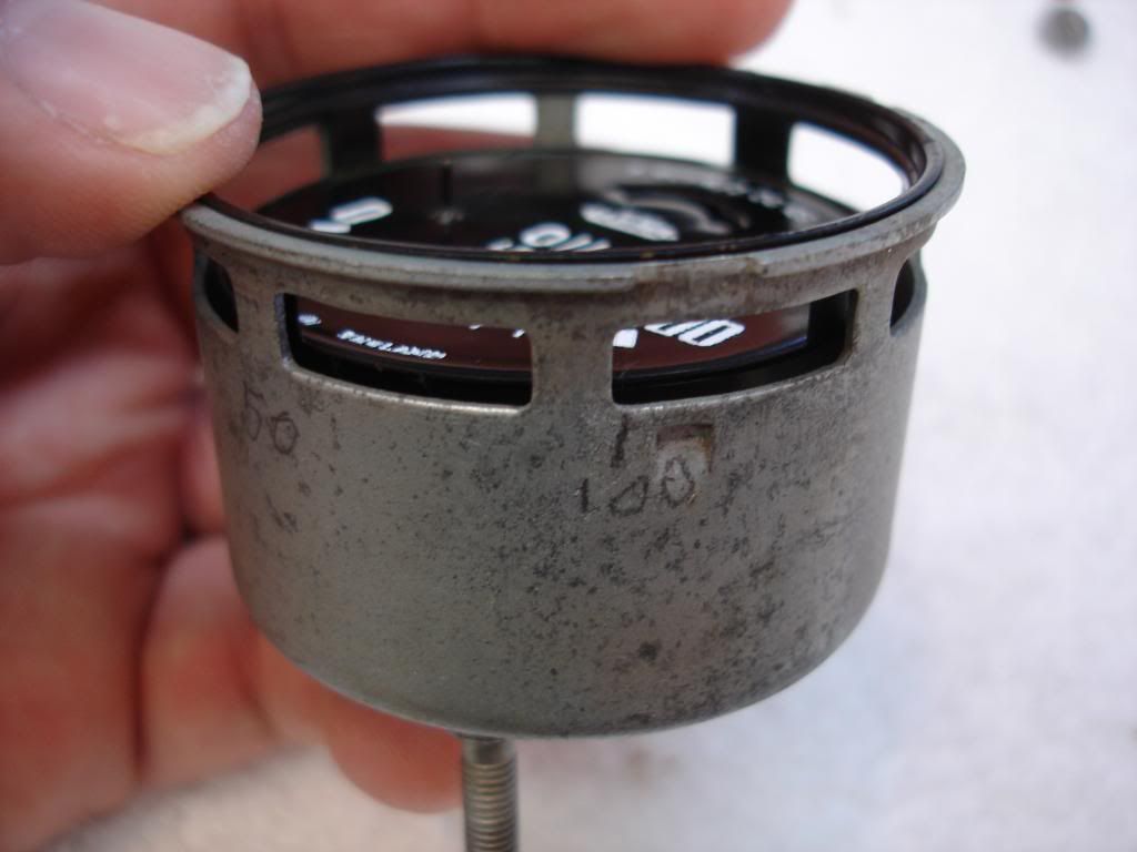
Calibrating is fairly simple compared to the fuel gage, but then anything is simple compared to that!! First, I placed the face on the case and marked the location of the 0, 50psi, and 100 psi. The face must come off to calibrate, so it is more convenient to leave it off and use the transferred marks:
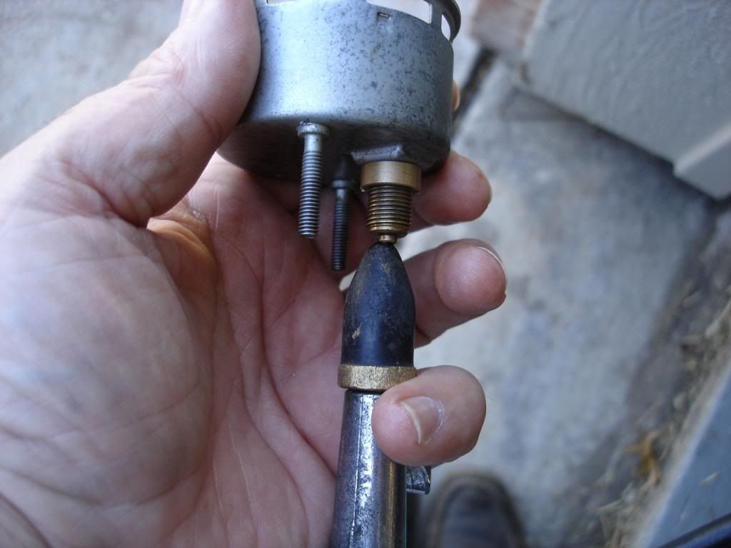
Now, I used my air hose with a gage and regulator. Just adjust the air to the pressure you want to calibrate, and input that pressure into the gage nipple using a rubber tipped nozzle.
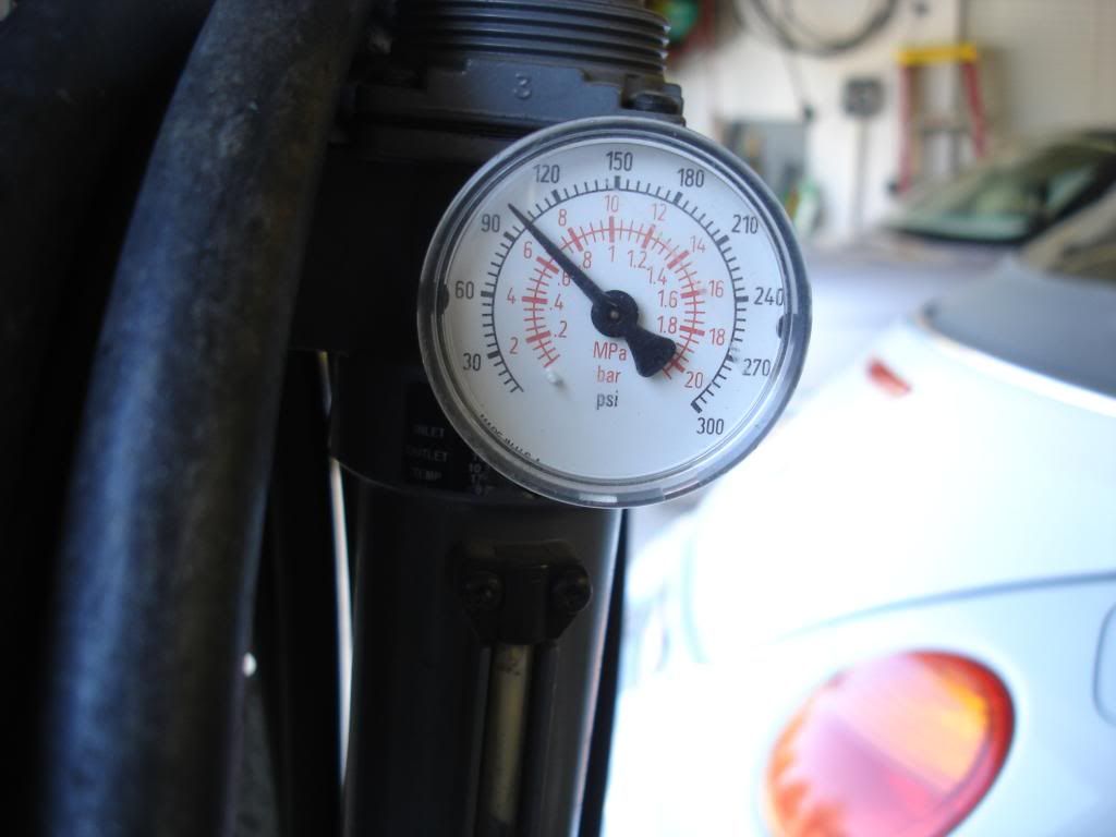
Bend the wire on the gland to set the "0" indication. Adjust the screw to get the 100 indication.
As with all our simple gages, I pick the number I want to be most accurate. In normal driving, 100 psi is not a usual number. I made the gage perfect at 50 psi, since that is midrange. For my gage, the best I could get was 50 at actual 50...but 90 indicated at 100 actual. That is close enough for me. If I had a couple hours, I might have been able to get it closer.
And, the reassembled gage:

It is super simple. The rounded gland is hollow. As oil pressure is allowed inside the gland, it tried to unwind and straighten out. The motion form this unwinding is transfered to the needle by a wire soldered to the gland. That's it!
This is a newer version of the gage. It has a few different details, but it is still exactly the same mechanism:

I removed the nut holding the mechanism in the case and bead blasted everything.

The earlier gage has an adjustment for sensitivity. You bend the wire to calibrate, but this screw is used to control the range of the needle.

And of course...there is a clock spring. The spring takes up the "slack" in the mechanism, so any play is takne up. Use care with it...

I taped the needle and spring before blasting.

Calibrating is fairly simple compared to the fuel gage, but then anything is simple compared to that!! First, I placed the face on the case and marked the location of the 0, 50psi, and 100 psi. The face must come off to calibrate, so it is more convenient to leave it off and use the transferred marks:

Now, I used my air hose with a gage and regulator. Just adjust the air to the pressure you want to calibrate, and input that pressure into the gage nipple using a rubber tipped nozzle.


Bend the wire on the gland to set the "0" indication. Adjust the screw to get the 100 indication.

As with all our simple gages, I pick the number I want to be most accurate. In normal driving, 100 psi is not a usual number. I made the gage perfect at 50 psi, since that is midrange. For my gage, the best I could get was 50 at actual 50...but 90 indicated at 100 actual. That is close enough for me. If I had a couple hours, I might have been able to get it closer.
And, the reassembled gage:

OP
CJD
Yoda
Offline
Now the ammeter.
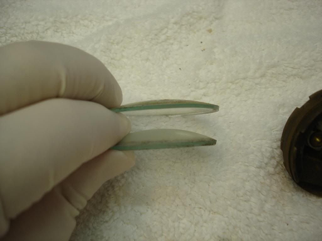
This gage is different...literally. It is not Smith, but Lucas. The glass on the front is less convex:
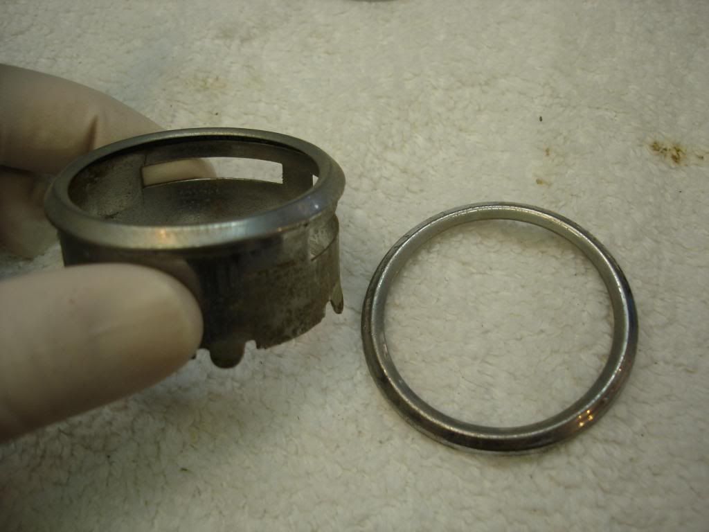
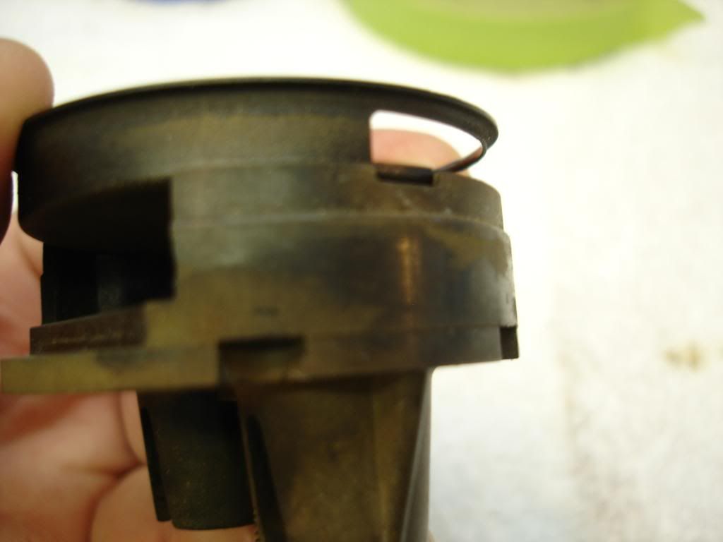
And, the bezel is actually the outside of the gage case too. Here is the ammeter bezel on the left, compared to the other gage bezels:
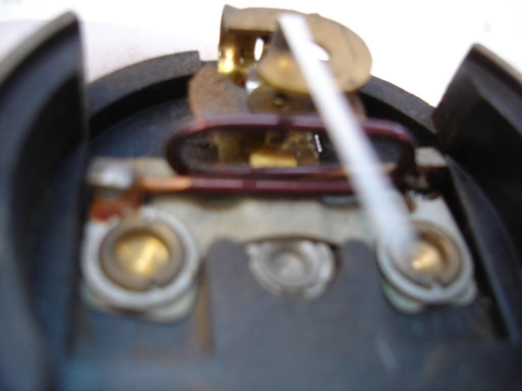
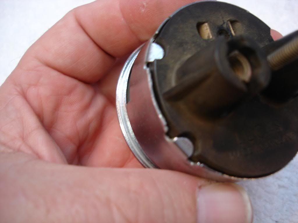
The inside of the gage is as simple as it gets. The needle is attahed to a steel plate. There is no spring to center, but rather a magnet that centers the needle. You have to bend the needle to center it.
This picture us blurry, but you can make out the gist. There is a single loop of thick wire. All the electrical load of the car must go through this loop. When it does, it makes an electromagnetic field that deflects the needle. That's it. No surprises. And no adjustments...hurray!
Again, painting the needle:
Cleaning the bezel/case:
Adding the face and light ring is very tricky. I couldn't do it and take pics, but suffice to say you have to balance the glass, seal, face, light ring...and then slowly and carefully lower the bezel over it all. It took a few tries to get it. Afterwards, re-crimp the bezel tabs.
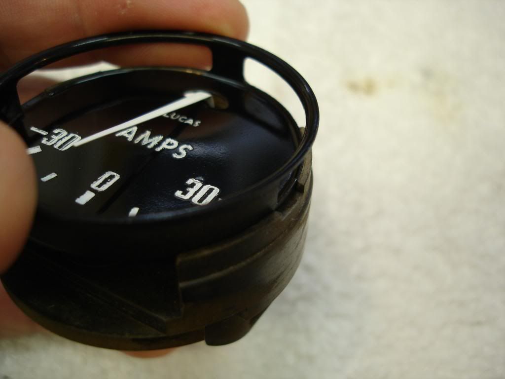
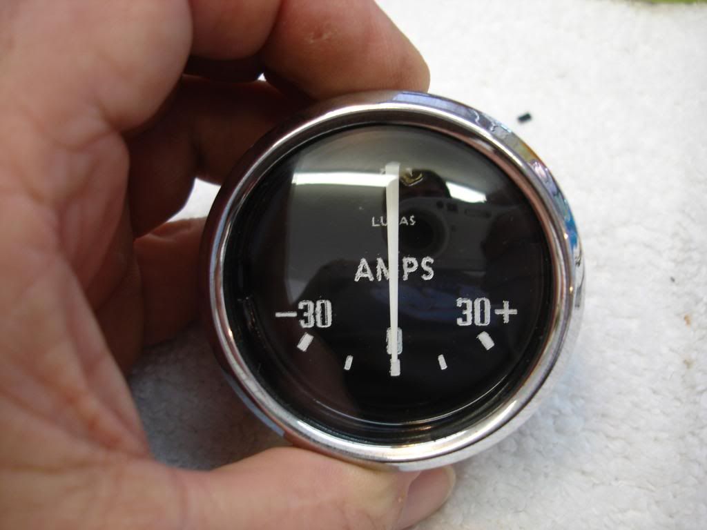
This gage is different...literally. It is not Smith, but Lucas. The glass on the front is less convex:

And, the bezel is actually the outside of the gage case too. Here is the ammeter bezel on the left, compared to the other gage bezels:

The inside of the gage is as simple as it gets. The needle is attahed to a steel plate. There is no spring to center, but rather a magnet that centers the needle. You have to bend the needle to center it.

This picture us blurry, but you can make out the gist. There is a single loop of thick wire. All the electrical load of the car must go through this loop. When it does, it makes an electromagnetic field that deflects the needle. That's it. No surprises. And no adjustments...hurray!

Again, painting the needle:

Cleaning the bezel/case:

Adding the face and light ring is very tricky. I couldn't do it and take pics, but suffice to say you have to balance the glass, seal, face, light ring...and then slowly and carefully lower the bezel over it all. It took a few tries to get it. Afterwards, re-crimp the bezel tabs.


OP
CJD
Yoda
Offline
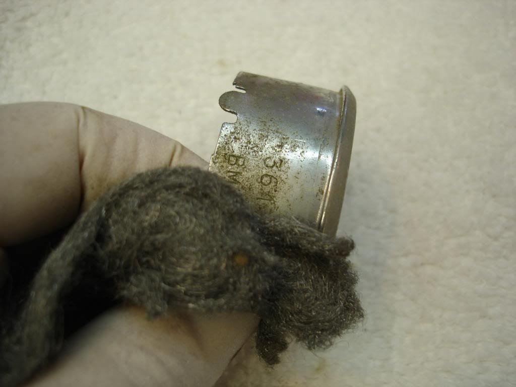
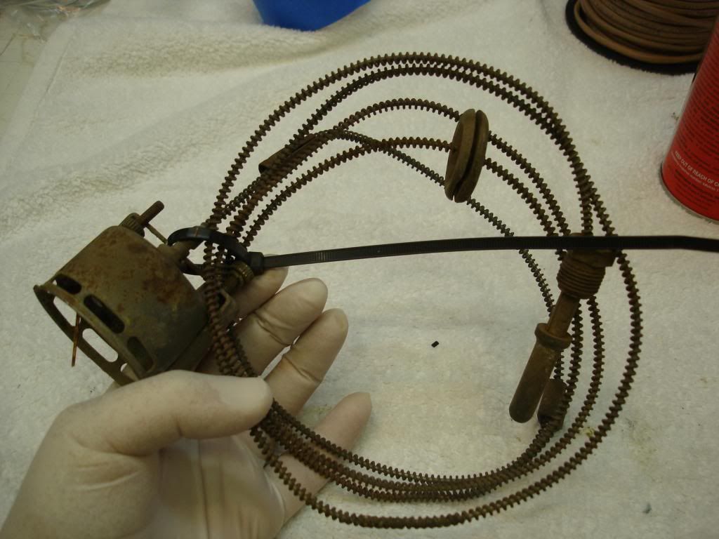
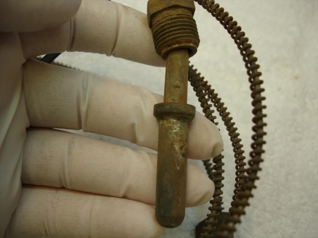
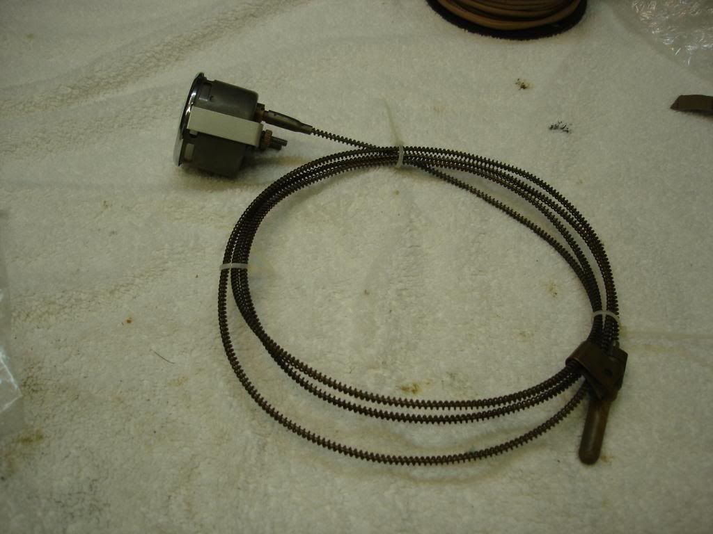
The final is the Temp gage. If your tube is crimped or broken...you are best to send it off. I will one day study how to fix a broken capillary tube, but I don't know now how to do it. The gages itself is identical to the oil pressure gage in mechanism and function. The only difference is the long capillary...that must be treated with kid gloves. Gently bend the capillary into a coil, removing any sharp bends. Tie lock it like this and leave it alone as much as possible. I did bead blast the bulb and tube, and sprayed with clear laquer on the tube only.
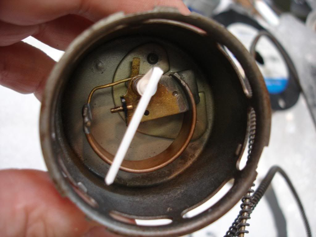
The mechanism can be removed from the case for cleaning, but the case will remain on the tube while you do it. Annoying, but not a problem.

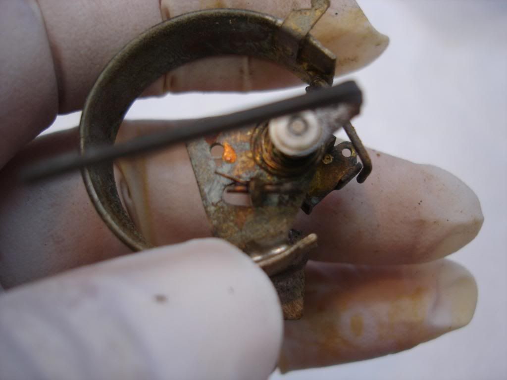
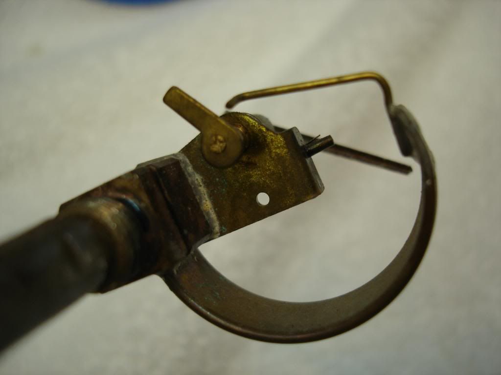
Again, the mechanism is just like the oil gage in design:
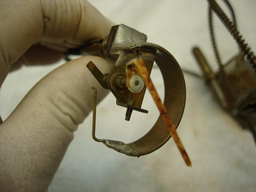
This is the wire from the gland, disconnected from the needle for cleaning. Notice there is no adjusting screw. You increase sensitivity by putting the wire contact point closer to the needle pivot point. Reduce sensitivity by moving the wire contact point farther out on the needle arm.
Once again, mark the outside of the case to match the face markings:
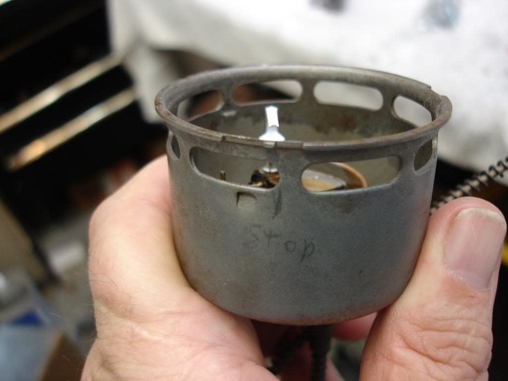
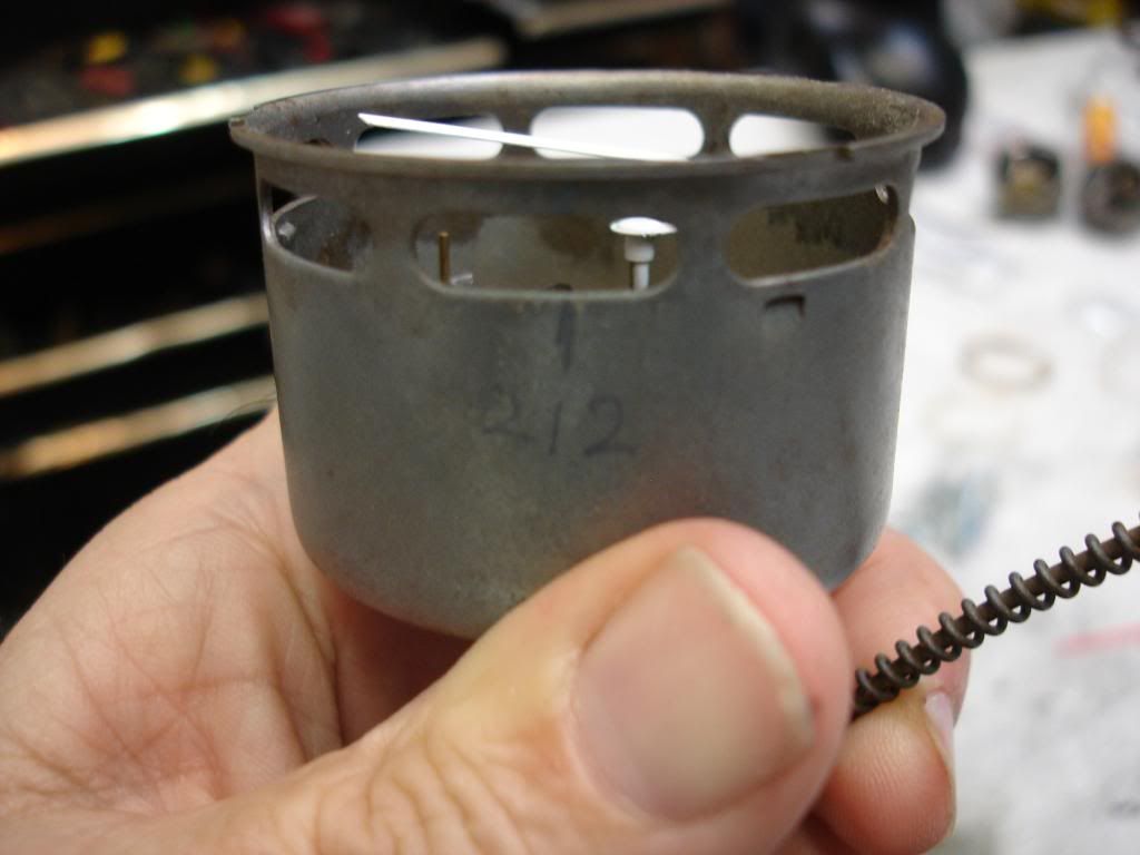
Calibrating is easy. The 212 degree mark is the one just below the full range, 230 degree mark. You boil some water on the stove...put the bulb in the water (not laying on the bottom though)...and adjust the needle to the mark. When you're happy with that, run some water in the sink and adjust it to body temp, give or take. Run the bulb in the stream and the needle should return to the 90 degree mark.
Bend the wire shorter or longer to set the 90 and 212. Move the wire contact point inward on the needle arm for more range or outward for less. Don't forget you have some adjustment at 90 degrees by bending hte needle slightly.
Assemble and you're done.
The mechanism can be removed from the case for cleaning, but the case will remain on the tube while you do it. Annoying, but not a problem.


Again, the mechanism is just like the oil gage in design:

This is the wire from the gland, disconnected from the needle for cleaning. Notice there is no adjusting screw. You increase sensitivity by putting the wire contact point closer to the needle pivot point. Reduce sensitivity by moving the wire contact point farther out on the needle arm.

Once again, mark the outside of the case to match the face markings:


Calibrating is easy. The 212 degree mark is the one just below the full range, 230 degree mark. You boil some water on the stove...put the bulb in the water (not laying on the bottom though)...and adjust the needle to the mark. When you're happy with that, run some water in the sink and adjust it to body temp, give or take. Run the bulb in the stream and the needle should return to the 90 degree mark.
Bend the wire shorter or longer to set the 90 and 212. Move the wire contact point inward on the needle arm for more range or outward for less. Don't forget you have some adjustment at 90 degrees by bending hte needle slightly.
Assemble and you're done.

