• The Roadster Factory Recovery Fund - Friends, as you may have heard, The Roadster Factory, a respected British Car Parts business in PA, suffered a total loss in a fire on Christmas Day. Read about it, discuss or ask questions >> HERE. The Triumph Register of America is sponsoring a fund raiser to help TRF get back on their feet. If you can help, vist >> their GoFundMe page.
  • Hey there Guest!
    If you enjoy BCF and find our forum a useful resource, if you appreciate not having ads pop up all over the place and you want to ensure we can stay online - Please consider supporting with an "optional" low-cost annual subscription.
    **Upgrade Now**
    (PS: Subscribers don't see this UGLY banner)
Tips
Tips

TR6 71 TR6 Ignition Light Stays On

brent615

Jedi Trainee
Offline
my ignition light is staying on as the car runs. i have had no problem starting the car, the battery seems to be charging well. it doesn't appear to be harming affecting anything but it must be on for some reason.

ideas and thoughts welcome....
 

kodanja

Obi Wan
Country flag
Offline
BAD GROUND?
 

martx-5

Yoda
Country flag
Offline
How is the ammeter reading? What does it read while the car is running and the lights and accessories are on?? If the ignition light stays on, that usually indicates that the alternator is NOT charging.
 

conan69

Member
Country flag
Offline
Could be the light control circuit in the alternator.
The Diode trio contols the light and is a weak link.
This as been the case on my 69 TR6 75% of the time.
 

amcboy

Jedi Hopeful
Offline
Just had this problem.

Traced it to the small connection on the ammeter.

A little ProGold and its happy again.


The light goes betweent he output of the Alternator and Battery.

So, if they are both at the same voltage there is no light.

If the Alternator fails, the battery is at 12V and the alternator at 0V. Light on.

Likewise if the battery dropped out of the car, the alternator would be at 12V, and the battery at 0V. Light on.

Try wiggling the small connector at the ammeter.

Then measure the voltage at the alternator to see if the thing is, ah, putting out.

Do you have the original 5 wire alternator or a 3 wire conversion?

If the 5 wire, then the loop wire (Brown with yellow) could be faulty.

Some places to start.
 

TR3driver

Great Pumpkin - R.I.P
Offline
amcboy said:
Traced it to the small connection on the ammeter.
<snip>
The light goes betweent he output of the Alternator and Battery.
Seems like your car must have been somewhat modified then. Normally, the light goes between the terminal on the alternator and the ignition circuit (white wire at ignition switch). That way, the light goes out when both the alternator and ignition are not powered. But the ammeter normally has power all the time (so things like the headlights and horns can work without having the ignition key on).
 

hondo402000

Darth Vader
Offline
you didnt put a MSD unit on did you? if so you got to install the diode or the light will stay on, I know, hours of checking wires until someone here made the comment and shazam it worked
 

amcboy

Jedi Hopeful
Offline
Randall, my car is stock and perhaps I was being too simplistic... Not knowing Brent615's skill level, I tried to simplify the concept.

However, in great expounded,difficult to understand, laborious, nearly complete detail:

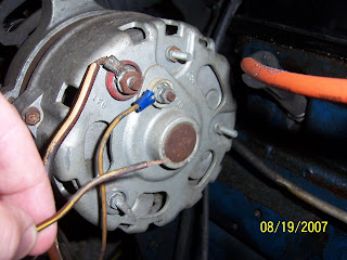
The small brown and white wire from the ammeter connects to the ignition switch, where, when the ignition is in the "on" or "run" position, the white wires (igniton, and the aforementioned promlematic always on light) connect to the battery via the ammeter and starter terminal. So, say, if the ignition switch were on and the engine not running the connection would be made thus:

Negative terminal of battery to ground to alternator via engine block and black wire from same, then brown with yellow wire to lamp to white wire to ignition switch to brown with white wire to ammeter, through ammeter to brown wire to starter lug to positive terminal of battery.


The headlight switch is fed from the ignition switch terminal that has the brown and white wire on it above (via a brown and white wire) , so it always has voltage and that current travels through the ammeter when a load is applied. For example the headlights or running lights...

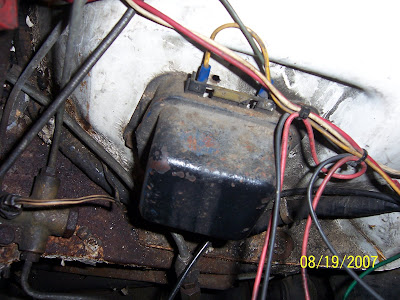
The horns, glove box lamp, interior lights,ignition key warning circuit, hazards, high beam lamp (in the speedometer) and trunk light (purple wires mostly) are all powered via the brown wire from the junction block (from the battery via the starter) through the fuse block and do not pass through the ammeter. Therefore none of these loads will cause the ammeter to move when activated.

The grounds or "common" for all of these items is to the frame/body/engine with the exception of the aforementioned problematic always on light.

So, theoretically, there could be a ground along the course of the brown and yellow wire from the alternator to the light. Its not likley to be on the white wire from the ignition switch to the light, because the ground would probably cause the engine not to run because the voltage to the points would be going directly to ground, rather than through the (resistance) load of the lamp. Electricity like water wanting to take the path of least resistance would likley choose the 1-2 Ohm coil over the (guessing here, but I can measure if necessary) 10 Ohm lamp.


So, while my earlier description was not entirely precise, its functionality was accurate to BASICALLY describe what's going on.

I will be happy to provide complete colored drawings if necessary.

/bcforum/images/%%GRAEMLIN_URL%%/cool.gif
 
OP
B

brent615

Jedi Trainee
Offline
over my head...you were right to keep it simple. wiring is far from my strong suit.

i did have a brown and yellow wire that was loosely hanging at the alternator a few months back (see pic). I must have connected back to the wrong point. I believe this is a Delco alternator. I can check later if needed.


100_2956.JPG
 

martx-5

Yoda
Country flag
Offline
That's an old Ford alternator. The voltage regulator is NOT incorporated inside the alternator. That means you have to have a seperate regulator somewhere, which also means that the charging circuit has been rewired. /bcforum/images/%%GRAEMLIN_URL%%/hammer.gif
 
T

Tinster

Guest
Guest
Offline
Brent'

I hope I'm not insulting you. Here is a wiring schematic
for a 1971 TR6. I keep my schematic in my car at all times
since I know squat about auto electronics but I'm good with
colors..

https://www.advanceautowire.com/tr2506.pdf

Again, I don't mean to insult you. I'm fairly brain dead
when it comes to auto wires and such. I make simple minded
testing devices to check out problems. I have several very
long #14 wires with alligator clips on both ends. When I
have doubts about a wire maybe having a grounding problem-
I unhook both ends of the suspect wire and connect my long
test wire to check it out. If the problem disappears with
my test wire hooked up; I replace the suspect wire.

Like I just did yesterday to my fuel gauge power wire!!

regards,

d
 

2wrench

Luke Skywalker
Country flag
Offline
First, sorry for this...

Second: If you turn off the engine, the light will
go out. No problem.

Third: Sorry, again.
 

TR3driver

Great Pumpkin - R.I.P
Offline
martx-5 said:
That's an old Ford alternator. The voltage regulator is NOT incorporated inside the alternator. That means you have to have a seperate regulator somewhere, which also means that the charging circuit has been rewired.
/bcforum/images/%%GRAEMLIN_URL%%/iagree.gif In fact, it's very similar if not identical to the alternator I used on my TR3A. Here's a shot of the voltage regulator mounted to the firewall. This is a later solid-state regulator, the one I originally used was much taller and had two relays inside.

I would suggest unplugging the regulator and see if the light stays out with the key on. If it does, replace the regulator.

PS the white stripe is not paint, but sunlight shining through the gap between the hood & body.
 

amcboy

Jedi Hopeful
Offline
/bcforum/images/%%GRAEMLIN_URL%%/iagree.gif I agree with Randall.

My wiring diatribe is now only applicable in principal.

Your loose wire is a bit of a pickle.

There is wee writing on the terminals of your alternator.

I can see it in your picture.

What do they say? Could maybe figure out where it goes.
 
OP
B

brent615

Jedi Trainee
Offline
You guys are GREAT!...and no offense taken Tinster. I wouldn't be on here 3+ times a day if I knew more, but I have learned some things tonight.

Update: It is a Ford alternator as everyone said, there is a regulator mounted on the wheel well with 4 connectors only two of which have wires. 1 is a green wire from the fuse block to the regulator and the other is a yellow wire from the regulator terminal marked "F" to the alternator connector marked "FLO". The two unused connectors on the rgulator appear to be marked "A" and "S".

Open/unused connectors on the alternator are "STA", "GRD" and one with no label. The only thing my brown/yellow wire will reach is the STA. Tried that and light stays on still.

Regulator
100_2958.JPG
 

TR3driver

Great Pumpkin - R.I.P
Offline
Interesting. Art will correct me if I'm wrong, but I think that means your setup has been wired Chrysler-fashion, with the regulator not detecting when the alternator is turning but simply applying field current whenever the key is on (and the voltage is below the set point).

I think what you should have is the brown/yellow going to one of the terminals on the regulator, which I think should be marked "I". (This is likely the terminal that currently has a wire from the ignition on it.)

Then there should be a wire from the STA terminal on the alternator to the regulator (probably the 'S' terminal but I'm just guessing). This is a low-voltage AC output that tells the regulator when the alternator is turning. One of the relays runs on this AC voltage; and when the voltage is high enough, the relay closes and applies battery voltage to both the warning light terminal and the alternator field (through the other, voltage regulator relay).

Then the "A" terminal should go to somewhere close to the battery, as it both supplies power to the regulator (and alternator field) and serves as a voltage sense input.

But ... are you saying the light comes on even if the brown/yellow is not connected ? That implies there is something else connected to it somewhere.
 

TR3driver

Great Pumpkin - R.I.P
Offline
Here's a diagram that might be helpful. Color codes are all wrong, of course, but it shows the connections between regulator & alternator. Also doesn't show your ammeter, but logically it would be in the lead marked "Large yellow/black" between the alternator and the junction block.
 

martx-5

Yoda
Country flag
Offline
TR3driver said:
But ... are you saying the light comes on even if the brown/yellow is not connected ? That implies there is something else connected to it somewhere.

/bcforum/images/%%GRAEMLIN_URL%%/iagree.gif The bn/yl wire comes right from the indicator light. That wire should be connected to the "I" terminal on the voltage regulator. If it's not connected to anything, it won't (shouldn't) light. That's how I read both the schematic that Tinster linked to, and the Ford diagram that Randall posted.
 
Similar threads
Thread starter Title Forum Replies Date
I TR6 TR6 ignition light faint - this can't be good Triumph 35
SCguy TR6 Ignition Timing with a timing light on a a TR6 Triumph 16
BillyZ TR6 1976 TR6 Ignition warning light Triumph 17
R TR6 Crazy Ignition Failure in TR6 engine… Triumph 7
C TR6 Ignition Switch for 1972 TR6 Triumph 1
L TR6 1974 Tr6 ignition switch Triumph 3
sundown TR6 TR6 electronic ignition Triumph 10
D TR6 TR6 Electronic Ignition Triumph 16
TLW1958 TR6 1972 TR6 No ignition cut off Triumph 2
M TR6 1976 TR6 Ignition problem Triumph 6
B TR6 71 TR6 Ignition/Starting Issue Triumph 13
O TR6 1971 TR6 Ignition Switch Swap Triumph 1
V TR6 TR6 Ignition Wires Triumph 14
D TR6 TR6 Ignition Switch Triumph 15
B TR6 71 TR6 Ignition Switch issues Triumph 5
H TR6 TR6 Ignition Key Triumph 3
S TR6 Ignition timing on TR6 Triumph 3
R TR6 Ignition timing on '72 TR6 Triumph 14
Steve1970 TR6 How do you replace the ignition lock, 74 tr6? Triumph 6
jjbunn TR6 TR250 Ignition Switch in my TR6 Triumph 13
J TR6 stuck again - ignition switch removal on a tr6 Triumph 14
2wrench TR6 No response at key ignition '74 TR6 Triumph 5
V TR6 TR6 ignition coil polarity Triumph 3
mrv8q TR6 '74 TR6 ignition switch woes Triumph 6
mrv8q TR6 '74 TR6 ignition switch fun Triumph 4
roofman TR6 1972 Tr6 ignition switch removal questions Triumph 5
jmayled TR6 TR6 No ignition / power Triumph 4
bighly Healey and TR6 ignition rotors Austin Healey 8
N TR6 TR6 Steering lock and ignition Triumph 1
K TR6 TR6 ignition switch wiring Triumph 1
AltaKnight TR6 TR6 ignition timing Triumph 6
Alfasudcrazy TR6 TR6 electronic ignition. Triumph 22
V TR6 TR6 Electronic Ignition Triumph 2
7 TR6 TR6 Electronic Ignition Triumph 1
C TR6 TR6 electronic ignition Triumph 2
B TR6 TR6 Electronic Ignition Conversion Triumph 10
C For Sale 69 Triumph TR6 Racecar Triumph Classifieds 0
mctriumph For Sale 69 Tr6 Triumph Classifieds 1
B TR6 TR6 block decking Triumph 2
A TR6 How many fuel filters-TR6 Triumph 25
Got_All_4 General Tech TR6 Transmission Troubles Pops Out of 3rd gear Triumph 2
J TR6 Repadding TR6 frame Triumph 0
S Wanted Need an HVDA conversion kit for 73 TR6 Triumph Classifieds 3
M TR6 Sorting out new TR6 Triumph 10
tr6nitjulius For Sale TR6 Clutch Master Cylinder $40 Triumph Classifieds 0
S TR6 '72 TR6 distributor issues Triumph 3
R TR6 Limit Mechanical Advance on TR6 distributor? Triumph 8
RonC General TR TR3 Shifter on TR6 Triumph 8
B TR6 TR6 convertible top frame Triumph 0
K TR2/3/3A The TR6 gearbox Ist gear.... Triumph 1

Similar threads

Top