• The Roadster Factory Recovery Fund - Friends, as you may have heard, The Roadster Factory, a respected British Car Parts business in PA, suffered a total loss in a fire on Christmas Day. Read about it, discuss or ask questions >> HERE. The Triumph Register of America is sponsoring a fund raiser to help TRF get back on their feet. If you can help, vist >> their GoFundMe page.
  • Hey there Guest!
    If you enjoy BCF and find our forum a useful resource, if you appreciate not having ads pop up all over the place and you want to ensure we can stay online - Please consider supporting with an "optional" low-cost annual subscription.
    **Upgrade Now**
    (PS: Subscribers don't see this UGLY banner)
Tips
Tips

Tri-carb PCV valve

  • Thread starter Deleted member 21878
  • Start date

John Turney

Yoda
Silver
Country flag
Offline
Hi Drone Dog,

Here is a writeup that presents what I had done to create a simple catch can (see shared link below). Although simplistic, it could be easily constructed and installed with the tube going to the air cleaner (in the picture) diverted to your copper manifold tube. Here is a picture of the mount used in my Healey (no modifications to anything).

Ray(64BJ8P1)

View attachment 57529

https://drive.google.com/file/d/0Bx4EjcJmfaScU29Fa0d0TWNXcm8/view?usp=sharing
Ray, Have you measured the oil collected by your catch can?
 

RAC68

Darth Vader
Offline
Hi John,

Not really. The Oil Catch Can was created to satisfy the extraction of oil and condensed noxious gases PULLED from the engine's bowels by manifold vacuum force and needed to have sufficient displacement for an extended period of light driving or a long run. Since there was no documentation as to how much oil volume to plan for, I chose a container that would be easiest to position and would fit nicely in the limited space available for convenience.

The situation the catch can is in today is as an extraction point for the standard system. As such, rising contaminated oil vapor buildup is pulled with almost nonexistent force (if any) of carburetor vacuum through the air cleaner as originally designed. However, it does function and condensed oil is found on the mesh and, after an initial 3 month test, less then a teaspoon of oil was collected. No signs of any oil or sediment, in access of the normal light coating purposely placed on the filter, was found in the filter mesh or any part of the carburetor. Keep in mind that I did not seal any other escape points (i.e.
oil cap, dip stick, etc.) but also never found any oil sediment around these either.

In the hopefully near future, If I find an appropriate PCV, I will put the original plan into action.

Ray(64BJ8P1)
 
Last edited:

mgtf328

Jedi Hopeful
Country flag
Offline
If you're worried about the pressue you could measure it by fitting a temporary T piece in the line and connecting a gauge or manometer. You can control the presurre by fitting a restictor in the line to the manifold connection. I did this for my MGTF. I drilled a small hole in a piece of round steel rod and rammed it into the pipe to the manifold. You may have to experiment a few times with diameter of the hole. I also fitted a flame trap from a Land Rover, this was filled with wire mesh and also helped stop oil from entering the manifold.
AJ
 
OP
D

Deleted member 21878

Guest
Guest
Offline
i found a cross reference to the PV770 at NAPA. the part number is 29228. SO i got one yesterday. it may not matter but i figured others have had success with this valve so may as well keep it the same.

Bob,
i also put a screw in the vent hole of the oil filler cap and made a seal for the dipstick. sounds like that is all that came in the kit, except for the valve and connections.

Ray,
i looked at oil catch cans yesterday and i found one i think will work. the one i found i do not think i will have to do any changes to the inside. Found cheaper ones but not sure how they actually work. probably would need to do some mods to the inside of them. the one i found looks to be a better system and under 30 bucks.

the trick is finding a place to put it and not look out of place. mine, being a tri-carb, eliminates the spot you used. then figuring plumbing that won't stand out.
 

RAC68

Darth Vader
Offline
Drone Dog,

Thanks for the NAPA PCV number 29228. I will purchse one to complete the original purpose for my catch can.

Ray(64BJ8P1)
 
OP
D

Deleted member 21878

Guest
Guest
Offline
Follow up:
Finished up the plumbing yesterday and started the car this morning. At first i did not think i had any vacuum at the oil filler cap but then realized you had to hold your hand there a few seconds to allow the vacuum to build. i am not sure how much vacuum i should get but it was a substantial amount, well it seemed like to me. you can definitely hear the suction if you pull the oil cap off. Since this is manifold vacuum, and not ported, i would guess i should have good vacuum at idle.

Speaking of which:
idle. i did not have any trouble with lumpy idle or uneven idle. in fact it may have been a little smoother. i did feel like the idle was now higher than before. but then i have fought the linkage allowing the idle to come down since i have put the engine in. So this cold day may have been part of the issue. after getting the car up to temperature, i did go back and balance the carbs again. i felt like adding the extra air into the front (tri-carb model) might thrown them off. i did have to add some throttle to the front carb to balance. but then i had to change the rear one a little also. So maybe i was just off from the last balancing act. I also have adjusted the mixture down one flat. We will have to get some runs in to check the plugs.

Oil Catch Can:
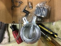
i did purchase an oil catch can. i bought it off of Amazon. i liked the way it seemed to work. on this can, there is an inner bit of tubing connecting to the inlet fitting. this tubing went down under a filter so all air had to go thru the filter and the air exiting is not going over any oil that may be collected. i did change the tube that was in the cannister. i have some 1/4 clear fuel line here and it felt more substantial than what was in the unit. And i wanted to make sure how far under the filter the tube went. did not want it so deep it could be in the oil it may collect. this can came with fittings for 5/8 hose and has a drain valve on the bottom. there is a plug on the top for a filter which i am not using. i figure every winter i can pull the plug and spray some cleaner down in there and drain it, which should keep the filter clean.

plumbing:
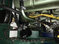
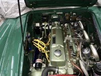
you can see in the pictures below i still ran a hose over to the rear carb. there is no air coming from that way. there is a "T" in the line and the side towards the carb is plugged. i did this to sort of keep an original look and to give the hose some support. the hoses run around behind the valve cover and over to the can on the left side. since the fitings were 5/8, this also allowed me to put the PCV valve behind the oil can.

View: all in it looks ok. i got the can in aluminum color but seemed like too much bling when mounted. i almost painted it the engine color but did not feel that would look right since the can is not attached to the engine. So i went black. small can, 2-1/2" dia and 3-1/2" tall.
fullsizeoutput_2c3.jpgfullsizeoutput_2c9.jpg

So not sure i have the right vacuum? how much is enough or too much? i guess if i have vacuum and it idles/runs fine, i am good? be interesting to see if my oil leakage at the rear seal stops.

i felt like i was done (silly me) and ready to go. but on my last start to check the idle, the front carb starts to run gas out the overflow. guess i got something in that grose jet. i will pull it tomorrow and if it still does act right, i think i have a couple of needle valves. it's always something.....

Oh and a special thank you to whoever it was that suggested putting pins on those air breathers. that sure saves a lot of time and hassle.
 

spinaway

Freshman Member
Country flag
Offline
Hi Drone Dog
Interested in what you done getting your PCV and catch tank rigged up on your Healey. I have a brother with a Healey Tri-Carb and he has been keen to put PCV in. He doesnt read these blogs so I copy this to him. Anyhow your picture showing the plumbing is helpfull. I can see the T piece in the line between the valve cover and the carb. But I cant figure our exactly where the two black hoses coming from the catch can go to ? Also where exactly is the PCV valve in your setup ?
Many Thanks
Des
 
OP
D

Deleted member 21878

Guest
Guest
Offline
Des,
the hose from the "T" goes to the in-side of the oil catch can. the out line from the oil catch can goes to the PCV and then on (3/8 hose from the PCV valve) to the copper tube on the right of the balance tube. it is run to the manifold port on the front intake. mine had a square head plug in there. pretty simple really. i used the NAPA part # 2-9228 PCV valve since no one around me had the PV770. the oil catch can i bought on Amazon for 30 bucks. probably not as nice as the Moss one but it looks like it should do the job.

the fittings from the manifold are this (and again it is what i could find locally). a 1/8 close nipple, a 1/8 fip to 1/4 fip adapter, a 1/4 mip to 3/8 compression adapter. the copper line is a 24" piece of soft copper tubing that was 3/8" OD.

hope that helps, pm me or email if you need any other info or pics.
 
OP
D

Deleted member 21878

Guest
Guest
Offline
i hooked a vacuum gauge to my setup today just to see what kind of vacuum i am pulling. (in a way kind of silly because i am not sure what i should be pulling)
inches/mg
idle 13-14 app 750 rpm
1000 rpm 15
2000+ 18-19
decel 23
accel 6

i did some reading last night and could not find a difinitive answer on what vac you should pull. or how to match that to a PCV valve.

one thing, after testing on the system, i hooked the vac gauge directly to the intake to see if there was a variance. i could not see any. i was thinking i would be pulling air from somewhere. (rear seal, dipstick) but it was not enough to show on the gauge.

also fixed my leak... i think. plan to start a new thread on that.
 

steveg

Yoda
Gold
Country flag
Offline
You could temporarily put duct tape around your dipstick and see if the vacuum changes - if you have your oil cap vent plugged, it would all be from the rear seal.

When I get my EGT probes installed will be looking at effects of leanness of PCV vs normal.

When I last ran my PCV, I put a couple of o-rings around the upper dipstick as an air seal.
 
OP
D

Deleted member 21878

Guest
Guest
Offline
Steve
i was thinking i could try and seal a little better but not sure i needed to.

My thought is that if there is some air coming in there, it is not enough to affect the idle. i know i don't have vacuum loss since my reading did not change with the PCV hooked up and hooking directly to the port.

Of course, i could not check my system under load but all the conditions i did test i still had vacuum. that plus a good idle may be all i need. certainly seem that what i read about most.

My only concern at this point is "can i have too much vacuum? and is there any harm i could do there?" Most of the newer PCV systems have a filter somewhere in the system to allow air in and circulate thru the engine. which i do not have.

there is not a lot of hard fast rules i have read anywhere about this. being a simple minded person i like clean cut rules. like you should pull this much vacuum and/or this much volume. maybe i am over thinking...

as soon as i get some seat time i can start looking at the plugs for fuel mixture issues.
 

RDKeysor

Jedi Trainee
Bronze
Country flag
Online
I'm surprised that I may be the first to identify the page in Norm Nock's book where he discusses PCVs. Page 98. The discussion includes identifying engines that might benefit from a PCV, etc., along with line drawings showing the valve functions.
 
OP
D

Deleted member 21878

Guest
Guest
Offline
in reading a number of other articles/info on PCV systems, most have a fresh air opening to the system. usually filtered air. allowing air thru the system to take out moisture, hydro-carbons, etc. from the engine. filtered, to keep out dirt.

From what i have seen here in these threads, and assuming most did them along the lines of what Nock's book suggests, there is not a fresh air intake to the system, unless maybe it is thru a seal. Even in the early, so-called open PCV systems, they left the oil cap vented to allow air in and out of the engine. (these caps had filters built in them) but Nock's kit suggests sealing the cap, right? And i have not seen info on any other fresh air intake.

From what i gather, and i may be off base, you leave an air intake in case of positive pressure during say high load driving. the pressure then has a place to go. Or after the car is shut off, gases have a place to vent.

wondering why Nock's system did not include this? what was his thinking?
 

John Turney

Yoda
Silver
Country flag
Offline
There really isn't a convenient place on an Austin engine for a filtered intake with a PCV system. One could put an inlet at the other end of the rocker cover, but now you've permanently modified the rocker cover.
 

HealeyBN7

Senior Member
Country flag
Offline
With all due respect I tried Norm's PCV valve(s) and I could not get them to function properly. It seemed that they either opened too easily or created to much of a vacuum leak regardless of orientation. The best solution I could come up with was a MGB valve. Moss carries new ones under part number 360-630. Works perfectly and I am ok with the look.

Dean
 

RAC68

Darth Vader
Offline
Hi All,

Maybe I have missed something. but I would expect a filtered air port in a newer engine’s PCV system would be there to allow sufficient engine bowel flow. Our engines are not NO-LEAK or tightly sealed. Our objective is to stop leaks by pulling outside air through these openings to eliminate the outward flow. Yes, a filtered air port to better manage vacuum and eliminate the possibility of over vacuum inducing additional conditions (i.e. increased cylinder blow-by) but, would that be a significant issue with a leaking Healey engine? Again, a modern engine's operation is highly monitored and controlled. Without these controls or even a vacuum profile for the Healey, placing an open filtered or unfiltered vent would be and experimental endeavor at best.

Just my thoughts,
Ray(64BJ8P1)
 
OP
D

Deleted member 21878

Guest
Guest
Offline
i have been looking at the air inlet issue and have modified my plumbing to what i think gives me an air intake without changing the looks... too much.

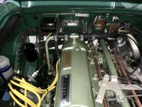
first, at the side cover, i took off the hose elbow and replaced it with a "T". i plugged the old vent pipe that goes up to the valve cover. (acutally at both ends) this makes that old vent pipe there just for looks really. back to the "T", the one leg goes to the side cover, the middle one is plugged to old vent pipe, and the other end comes up and goes to my catch can. From there of course it goes thru the PCV and on to the manifold port.

since the valve cover "T" is now plugged on the vent pipe side, the other side is left open and connected back to the back of the air breather. (stock look) this should now be sucking air in and gets some filtering there. i also rolled up some foam filter material and put it in the hose for a little extra filtering.

with this setup i should be pulling air from the breather, thru the valve cover, thru the engine and on to the oil catch can.

i was concerned about how much air i would pull thru this hose. (5/8" opening) might be too much to keep a vacuum in the oil pan or control air to the PCV. So i restricted the opening in the hole to 1/8" with a fitting in the hose. Not sure why i chose that size. just figured it was a place to start and i had the fitting. i can adjust that smaller or larger.

good thing is, if i do not like it, i can change it back by just pulling the rubber plugs and putting the rubber elbow back at the side cover.

i also thought about just putting a rear side cover in the middle for another hose connection. probably a cleaner look (too many hose clamps at that lower "T") but the side covers are way too expensive, if you can find a rear one.
IMG_0767.jpgfullsizeoutput_2d0.jpg
i need to reposition the catch can to get the pipe as straight as possible. i have some options there. and then, of course, i need to test.
 

RAC68

Darth Vader
Offline
Drone Dog,

I am now wondering what your objective is for your installation of a PCV. If it was to eliminate oil leakage out of the rear main, I believe you have just eliminated that result by introducing freer air flow (even with your restriction) though your port. In fact, if your restriction is not sufficient to maintain vacuum, it can be considered a vacuum leak and may even reduce draw through your carburetors. You have done a great looking well thought implementation but I am now unclear as to the purpose for your PCV implementation?

Ray(64BJ8P1)
 
Last edited:
Similar threads
Thread starter Title Forum Replies Date
B PCV Valve Tri Carb Austin Healey 11
Zitch SOLD!! SOLD - Tri-Carb Exhaust manifold for a 3000 Austin Healey Classifieds 0
T Air Filter Recommendations for My Tri-Carb Austin Healey 7
HealeyPassion For Sale Tri-Carb Complete Set including manifolds Austin Healey Classifieds 13
Healey Nut Tri-Carb Throttle Controls Austin Healey 4
D Tri carb: order of installation question. Austin Healey 5
Healey Nut Tri-Carb Project Austin Healey 213
CLB62 1962 BT7 Tri-Carb for sale on BaT Austin Healey 2
D 62 tri-carb upper fulcrum pins Austin Healey 4
M engine stutter of rebuild BT7 engine [tri-carb] above 2500 rpm Austin Healey 27
lbcspinners 1962 Austin-Healey 3000 Mk II BN7 Tri-Carb 2-Seat Roadster: for sale on BaT Austin Healey 2
D Grose valves / Tri-carb Austin Healey 11
D 62 tri-carb fuel line connection Austin Healey 10
C Tri carb Austin Healey 7
T Tri-carb questions. Austin Healey 10
J BT7 [Tri-Carb] Restoration Upgrades Austin Healey 2
D 62 tri-carb tuning question Austin Healey 8
D BT7 Tri-Carb Distributor Cap Austin Healey 9
D BT7 tri-carb linkage set up Austin Healey 23
D BT-7 tri-carb Two more questions Austin Healey 18
D BT-7 tri-carb ring gap Austin Healey 10
D BT7 tri-carb installing my crank Austin Healey 4
D 62 / BT7 tri-carb engine Austin Healey 16
D 62 tri-carb wiring harness Austin Healey 10
HealeyPassion Tri-carb intake manifold balance tube size Austin Healey 10
steveg Rare colored tri-carb BT7 on eBay Austin Healey 13
davidb AH 3000 tri-carb throttle shafts Austin Healey 13
W Barrett Jackson Auction 62 2 Seater Tri-carb only brings 48k Austin Healey 19
Norman Tri carb - overheating issue ???? Austin Healey 10
K Tri-carb help Austin Healey 11
K Tri-carb help please Austin Healey 0
AH67 62 MKII Tri Carb, done with some pictures Austin Healey 9
M WTB: Tri Carb Choke Linkage Parts Austin Healey 8
BoyRacer What are MK II [tri-carb] 2 seaters selling for? Austin Healey 12
D BT7 Tri carb Backfire Austin Healey 2
M Tri Carb Camshaft Austin Healey 4
B tri carb problems Austin Healey 17
B Gas mileage Tri-Carb Austin Healey 2
A tri carb on ebay Austin Healey 14
C Cold air box for Tri Carb 3000 BT7 ??? Austin Healey 9
G tri carb vapor lock Austin Healey 30
J Seeking tri carb help Austin Healey 16
M 100-6/ 3000 tri carb set up Austin Healey 13
Patrick67BJ8 Ruddspeed Tri-Carb Set-up Austin Healey 9
6 BN7 tri-carb will not start Austin Healey 7
6 BJ8-BT7 Tri-carb Conversion? Austin Healey 7
C Tri - Carb assistance ! Austin Healey 5
Dave Richards WOW! a "RARE" tri-carb Austin Healey 12
C AH 3000 Tri-Carb conversion. Austin Healey 4
V Choke cables for tri-carb Austin Healey 5

Similar threads

Top