Hey Guest!

 Hey - did you know if you click on the title of a thread it will take you to the first unread post since you last visited that thread?
 but were afraid to ask:
  STOP!! Never post your email address in open forums. Bots can "harvest" your email! If you must share your email use a Private Message or use the
  smilie in place of the real @
 Pretty Please - add it to our Events forum(s) and add to the calendar! >>
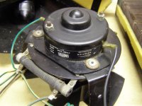
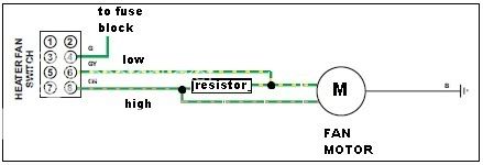
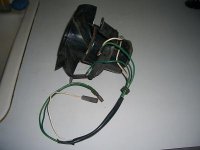
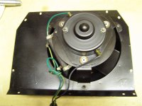
I need your help. My heater blower has always worked. I had the green/yellow wire and green/purple wire hooked up to the switch. When I took the heater out, I noticed that it has a white wire (same length as the two green wires) that has never been hooked up. The motor has one wire going from the motor to the resister. Then there is another white wire going from the motor that was never hooked up to anything. Anyone know what the purpose of this is? Is this a ground?
Kevin
Kevin