Hey Guest!

 Hey - did you know if you click on the title of a thread it will take you to the first unread post since you last visited that thread?
 but were afraid to ask:
  STOP!! Never post your email address in open forums. Bots can "harvest" your email! If you must share your email use a Private Message or use the
  smilie in place of the real @
 Pretty Please - add it to our Events forum(s) and add to the calendar! >>
bcbennett
Senior Member
Offline
Hi all,
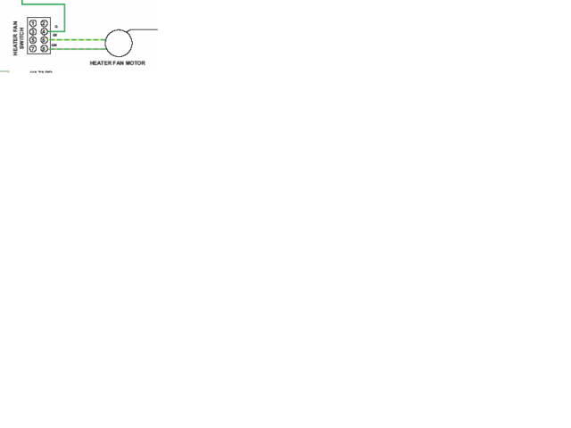
Just replaced my '74 TR6 heater unit with one that is rebuilt and ready. The previous owner had all the leads from the switch disconnected, and now, when I try connecting various combinations of the three wires (one hot, one low-speed, one high-speed), my fuse keeps blowing. I see two side-by-side connectors above the two vertical connectors, and I assume the hot wire goes to one of the upper prongs. Am I right? Help!
CB