• Hey Guest!
    British Car Forum has been supporting enthusiasts for over 25 years by providing a great place to share our love for British cars. You can support our efforts by upgrading your membership for less than the dues of most car clubs. There are some perks with a member upgrade!

    **Upgrade Now**
    (PS: Upgraded members don't see this banner, nor will you see the Google ads that appear on the site.)
Tips
Tips

TR2/3/3A TR3A brakes

TFB

Jedi Knight
Country flag
Offline
my Tr3 came with new brake lines on chassis,looking like the only new line I needed to run was from the master cylinder to the installed 4way connector.
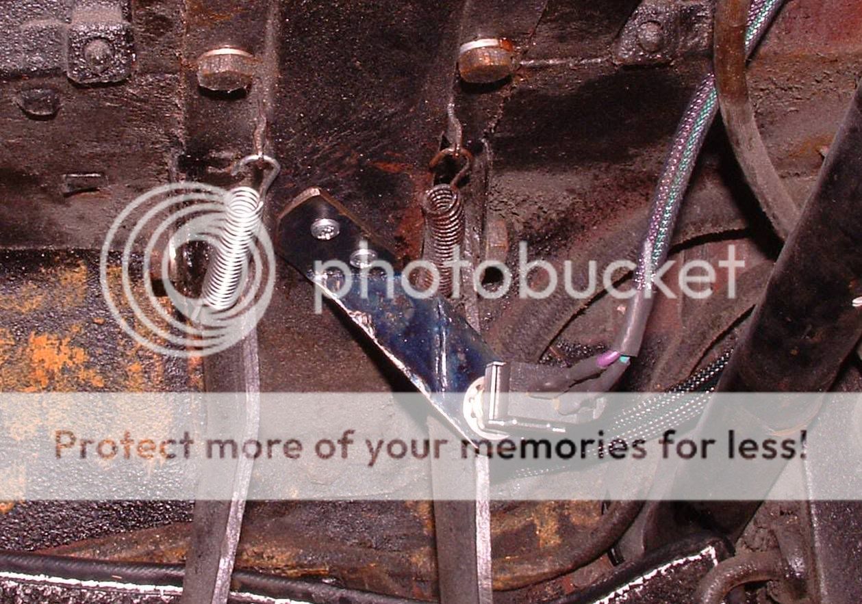
However with 4way in right front,and 3way tee in back,I see no place for brakelight switch.Moss shows 5 way ,which I guess is the one I need if I dont add an extra tee.
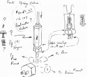
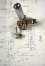
Also It looks like the MC line goes into the top of the restrictor?
Also is there a diagram of the restrictor showing internals and direction of installation,as I am concerned if this restrictor is installed correctly.
Thanks
Tom
 
Here is a sketch of mine from 1987.
 

Attachments

  • 22202.jpg
    22202.jpg
    52.6 KB · Views: 336
Here is a photo. The long end is straight up and the hydraulic brake switch faces towards the front of your TR.
 

Attachments

  • 22203.jpg
    22203.jpg
    33.4 KB · Views: 323
TR3ResidualPressureValveexploded.jpg
 
Tom, the 4 way connector on the chassis was used on TR2/early TR3 front drum braked cars, which didn't have a restrictor valve.

Front disc braked late TR3/3A cars need a 5 way connector, which has a top female thread for the restrictor valve. The RV fits vertically with the male thread end down into the connector. Then the brake line from the master cylinder goes into the top female thread of the RV.

Repop stop light switches don't seem to last long, so an option is to plug the hole in the connector and mount a modern stop light switch on the pedal box.

The RV should be taken apart and cleaned. There is a cross section view of the internals on page 191 of the Haynes TR2-4A Triumph Owners Workshop Manual, if you have one.

Regards,

Viv.
 
Don,Randall,Viv,
Thanks for info, this is exactly what I was looking for.I have taken the valve apart and it was cleaned and after looking at posted pics appears to be in the right position.
I dont have the 5 way so I would not have to plug if I relocate to mc box.
What is the easisest way to do this?Screw it into the mc between the pressure line ? Or do mean Micro mechanical swith that moves with pedal or linkage?
Also Viv mentioned repop switches dont last long,do you mean Moss repop,as opposed to over the counter universal type repalcements?
Thanks again
Many more questions to follow
Tom
 
I found that none of the hydraulically operated switches would last for long (either reproduction or generic replacements), possibly due to the uprated (2357) bulbs I use for brake lights, or perhaps they don't like DOT 5. But the vast majority of cars use mechanically operated switches, and these seem much more reliable.

Here's a shot of a switch from some other car (sorry, don't recall which one offhand) mounted on my pedal box.
P3170005.jpg


However, for the TR3, I decided I wanted it out of view, so I made a small bracket and mounted it under the dash (so it rides on the brake pedal).

Also, just my opinion, I don't like the function of the "restrictor" valve (which strictly speaking is a residual pressure valve), as it makes the front brakes drag lightly all the time. So I removed the plunger and spring. The only downside is that you may find the pedal lower after "spirited" driving, which can be disconcerting if you aren't expecting it. There is a better solution, IMO, in the form of spacers to go inside the front hubs https://www.zeni.net/trf/TR6-250GC/119.php?s_wt=1680&s_ht=1050 but I haven't bothered to install mine yet.
 
Hi Randall

Any chance you could post a photo of the under dash bracket and mechanical switch for brakes? Would be very helpful. Thanks

Pat
 
Kind of dirty under there, but here it is.
DSCF0029_crop.jpg
 
Randall,thanks for info.
I was trying to figure the purpose/function strategy of the restrictor.to me looked more like a check valve mounted backwards,or something that should be for back brakes or front,not all four..
Disc brakes always drag a little.
I will have to wait til tonite to see spacer pics,restricted access at work to photo sites.
I am very familiar with mechanical micro switches and have a large assortment at work to pic thru.Since the TR3 has no relays all witches carry full end device load/current,so maybe repro swithces are for modern cars ,swithing only control circuit of relay,although I would think two small brake light bulbs would not be an issue.Now to check wattage of bulbs and find suitable switch.
Thanks
Tom
 
TFB said:
I was trying to figure the purpose/function strategy of the restrictor.to me looked more like a check valve mounted backwards,or something that should be for back brakes or front,not all four..
Disc brakes always drag a little.
Yeah, but with the RPV they drag more. What it is supposed to do is hold a small amount of pressure (like 5-10 psi) in the braking system even when the pedal is released. Thus if the spindles flex (which moves the brake rotor sideways in the caliper), the pressure on one piston will force the other piston to extend (in effect tracking the sideways motion of the rotor), instead of pushing fluid back into the reservoir.
<div class="ubbcode-block"><div class="ubbcode-header">Quote:]although I would think two small brake light bulbs would not be an issue.Now to check wattage of bulbs and find suitable switch. [/QUOTE]
Something to keep in mind : Like most if not all incandescent bulbs, the 'cold' resistance of the filament is much lower than when the bulb is lit. This results in a large "inrush" current when the brake switch is closed.
 
FWIW, I added a relay to the brake light circuit, but then I am still using a pressure switch and I have 5 brakelight bulbs.
 
Geo,
FIVE brakelight bulbs?
2 in the tail lights, 2 in the turn signals (doing double duty)
Where is the 5th one? (I'm assuming a TR3)
Frank

FWIW my 4 are all LEDs so high current isn't a concern.
 
Hi Randall

So is your switch set up so that when you push on the pedal, the pedal moves away from the switch, closing the circuit and lighting the lights? The switch is normally closed and the circuit is open (lights off) when the pedal is in resting position?

Pat
 
PatGalvin said:
So is your switch set up so that when you push on the pedal, the pedal moves away from the switch, closing the circuit and lighting the lights? The switch is normally closed and the circuit is open (lights off) when the pedal is in resting position?
Yes, that is exactly right. The switch is actually a standard brake light switch from some American car, although likely a TR6 switch would work just as well.
 
Perfect. I'll stop by my FLAPS and see what switches they may have that would work for this. Looks like an easy mod that would be a big improvement. You're not running these brake lights through a relay, right? Just throught the switch.

Pat
 
Pat,
I saw a pretty nice switch on ebay today that has lots of mounting/adjusting flexability,for about 8 bucks and shipping.Google welder joes ebay.I would post link but I need some training.
Tom
 
PatGalvin said:
You're not running these brake lights through a relay, right?
Well, actually, I'm only running the original brake light (which on my TR3 is a single bulb mounted in the center) directly from the switch. The switch would no doubt handle all three bulbs; but I have relays wired in for the other two, so they can do triple duty as stop/turn/tail lights even though they only have two filaments (similar to the way American cars worked back then).
 
Back
Top