• Hey Guest!
    British Car Forum has been supporting enthusiasts for over 25 years by providing a great place to share our love for British cars. You can support our efforts by upgrading your membership for less than the dues of most car clubs. There are some perks with a member upgrade!

    **Upgrade Now**
    (PS: Upgraded members don't see this banner, nor will you see the Google ads that appear on the site.)
  • When posting a classified ad, you MUST select a prefix from the drop-down next to the subject line. If you don't you will get an error and your ad will not be posted!
Tips
Tips

TR2/3/3A TR3A brake light activation

TFR

Jedi Trainee
Offline
Have a restored TR3A and of course it still has Lucas electrics. However all the wiring is new and nicely attached to each service.
My concern... People are constantly telling me my brake lights aren't working but when I press hard on the peddle they illuminate. I hate to have to press hard to get them to light so I'm wondering if anyone knows why it takes a lot of pressure to get them to work? Is there an adjustment? Is there another way to activate them? Could there be a fluid problem? The brakes work very well.
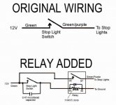
I was thinking of bypassing the original sensor and adding a micro switch on the peddle / linkage.
 
Lots of folks do that, Larry. Original Lucas pressure switches seemed pretty durable. Some replacements? Less so. Also, there's been some "discussion" about the possibility that use of silicone brake fluid can affect these switches, but I don't know that it's ever been conclusively proven.
 
I just replaced my pressure switch. Likely the original, it still functioned but took a hard romp on the pedal to light them up.

The new switch (Moss) works with a very light touch -- a major safety improvement IMO.

I have added a relay to the brake lights because I have 5 of them (2 stock, 2 via double filamant bulbs in the turn signal fixtures and a magnetic-base towing light as a high-mounted brake light). I have also heard that the replacements are not as durable... perhaps the relay will prolong the life of that part.

I use the silly-cone grape juice but am doubtful that was a factor inasmuch as so many cars with DOT3/4 seem to suffer the same problem.

<span style="font-style: italic">Said relay. Used a period correct metal can relay wired by rerouting the existing wires and adding a couple more. Used correct color-codes and bullets so it looks more or less appropriate.</span>

Brake%20Light%20Relay.JPG
 
I've had several switches fail that way on my TR3A; just keep taking more and more pressure to activate the brake lights.

Got so frustrated with the problem that I eventually converted to a mechanically operated switch mounted on the pedal box (ala later TR4). Looked awful, but dead reliable.

For the project TR3, I've added relays to the stock switch, I'll see how that holds up. Still looks awful, but mostly hidden out of sight. And now the corner lights serve triple duty as brake lights, turn signals and tail lights.
 
To reinforce what Andrew says, I had the same complaint on my recent convoy to Rogers, Arkansas. The guy behind me nearly rear-ended me a couple of times. And YES, I have synthetic hydraulic in my system.

I mentioned this to my mechanic, who also threw this into the equation: my car has complete TR6 brakes and front suspension. Everything. In putting this car together, the builder may have omitted the Residue Pressure Valve that keeps pressure on the brake pads. This part was installed to prevent the pads from moving away from the discs during turns, and would maintain about 3 lbs of pressure on the pads. Back in the days of the gasoline crunch, you could remove this valve so that you could move the pads off the discs with a few turns of the wheel. Of course, the trade-off is a little better gas mileage for a little less brake response. So, the next time I am in his place, we will take a look and see if it is there.

Whether it is there or not, I will probably go in for the electric switch on the pedal, as I plan on attending a wide range of Triumph events.

Think about it. How could you make something as simple as a brake light any more complicated? Easy: let's make it HYDRAULIC. Of course, with satellites now, we could transmit from the brake pedal, have it bounce off a satellite back to a DISH on each brake light.

P.S. I would want my pair of dishes to be hydraulic.
 
I'm holding to my basic theory that "original" or NOS switches were/are better! Soon after I bought my '62 Herald 1200 in 2002, I discovered that the brake lights were iffy at best. Turns out that one of the two "blades" on the switch had pretty much completely broken off. (Imagine that, on a part then only 40 years old!) Needing something pretty quickly, I took an original switch off a '60 Herald parts car, a car that had been sitting around for many years. It's worked ever since!
 
I had to replace a couple of those hydraulic switches on my 1958 TR3A over the last 19 years (102,000 miles) and I asked my neighbour who has a lathe to turn the end off a couple of switches. We found that the side remote from the silicone fluid was still dry. This is the side that looks like a penny and is made of shiny copper (WHEN IT'S NEW). But when they failed, the far side (dry) that the pressure forced against the contact to make the rear red brake lights come on HAD TURNED BLACK all over that copper "penny" and would no longer conduct electricity.

Once when I had to change one, I checked the old one with the air from my air compressor and no amount of pressure up to 100 psi would make it work. I checked the new one plus the new extra I had ordered to carry as a spare. The compressed air would switch them both at about 20 psi. So I installed one and put the spare in my took box to carry with me. Five years later, the switch failed. So I removed it and re-checked it and 100 psi would not switch it just after 5 years of use. So before installing the spare switch, I re-checked this spare one I had been carrying for 5 years and you know what ? It would not make electrical contact at 100 psi and it had never been used.

I spoke to the supplier (one of our big three) and he replaced both defective ones for free.

I never figured out why they don't make that copper penny contach disc out of stainless steel so they will last 50 years instead of 5 years.

BTW, I have wired in a tiny micro-switch on a small bracket up above the brake pedal and it would only take me a minute to connect this if my present hydraulic switch was to fail. No one can see it - it's so small and when I push forward on the brake pedal, the hanging arm which is suspended from above, moves forward to close the "normally open" micro-switch.
 
I've made a nice bracket out of steel and am going to mount a mini-micro switch onto bracket. Then mount the assembly onto the brake/clutch master cylinder steel housing. Then add wires to the hydraulic switch wiring connections, then to the micro switch. Hopefully the "brake lights aren't working" warnings will cease.
 
I have been using a metal Lucas early TR4 switch mounted on the pedal box of my TR3 as it is on an early TR4. It's been working well for the past four years. Hope it continues working.
 
Aloha,

My experience is similar to Don's. I have dissected several failed hydraulic brake light switches and have not found any indication of brake fluid fouling the electrical contact side of the switch. The cause of the failure is severe pitting and carbon fouling of the contacts. I have used silicone brake fluid in my LBCs for about 25 years and don't think that is the cause of the failure. I think a contributing factor is that our cars generally are equipped with dynamos and use DC current where modern cars use alternators and AC current. The amp draw with DC brake lights is higher than an AC circuit. Most of the currently available hydraulic switches are light duty compared to the originals. Installing a relay in the brake light circuit and a capacitor across the brake light switch contacts (arch suppressor) will extend the life of the switch. Below is an excerpt from an article by Dave Dubois that explains how to do it. Even though it refers to MGs it does work in my TR3 also.

"Installing a Brake Light Switch Relay

The replacement brake light switches sold today are extremely light duty and don't hold up to the 3 amps drawn by the brake lights for very long before the contacts burn again (I have had them burn in just two weeks). Adding a relay to the brake light circuit will remove the heavy current from the brake light switch.
The relay to use is a general purpose 30 Amp automotive relay, sometimes known as a Bosch relay. They are available from Radio Shack and most auto parts stores. The relay can be mounted anywhere that is convenient. I mounted mine close to the original brake light switch, but it can just as well be mounted in the trunk (for the MGAs or MGBs), close to one of the tail light/brake light assemblies (if you do this, you will need to bring a source of 12 volts, other than the 12 volts that is switched by the brake light switch, back to where the relay is mounted). In the accompanying diagrams, I show a 0.47 microfarad capacitor across the contacts of the brake light switch and a diode across the coil of the relay. These are optional parts and can be left out if you wish. I added them as additional protection for the brake light switch. The capacitor is just soldered across the switch terminals. The diode can be soldered across terminals 85 and 86 of the relay. The advantage of the capacitor is that the capacitor acts as an arc suppressor and the diode collapses the field of the relay coil, eliminating any inductive surge across the brake light switch when it opens.

David DuBois"
 

Attachments

  • 18501.jpg
    18501.jpg
    32 KB · Views: 2,136
I gave up on the aftermarket brake switches 20 yrs ago when I went
to Dot 5. The mechanical switch on the cockpit side of the petal
has never failed me. I recently converted to LEDs on both the the
rear turn signals and tail lights. When I step on the brakes,
everything lights up! The only thing I miss is the "self checker"
for brake lights, the amp gauge. The LEDs don't draw enough power to
move the amp needle to a slight discharge. I'll have that solved by
the drive to TFest in SLO.
See you there !!
FRank
 
MGTF1250Dave said:
... I think a contributing factor is that our cars generally are equipped with dynamos and use DC current where modern cars use alternators and AC current...

Alternators have rectifiers (diodes) in them that convert the AC to DC. It's the only way to charge the battery.
 
Hey Frank and JFS! Could you please post photos of your modifications? From what I have read, this TR4 method seems to be the way to go, and I would sure like to see a picture of it!

Thanks in advance.

As usual, this forum is loaded with good ideas.
 
JFS said:
I have been using a metal Lucas early TR4 switch mounted on the pedal box of my TR3 as it is on an early TR4...

An odd thing is that if you take a close look at that switch I think you'll see it isn't Lucas but rather Delco.

At least that is how the original rectangular grey switch is on my TR4 and others I have seen.

Made in England, but by Delco... maybe that's the key to long service.

Delco%20Switch.JPG
 
martx-5 said:
Alternators have rectifiers (diodes) in them that convert the AC to DC. It's the only way to charge the battery.
And in a very real sense, DC generators also generate AC internally. They just use a mechanical rectifier (aka commutator) to convert it to DC, instead of solid-state diodes like an alternator does.
 
Dave, the drawing is for a positive-ground car, right?

Otherwise, if negative is ground, unless my poor old dramaged bain is letting me down again, the diode would short out the relay coil and it would not magnetize.
 
Aloha John,

You are correct, that is a diagram for a positive earth car. Here is one for a negative earth:
 

Attachments

  • 18507.jpg
    18507.jpg
    28.8 KB · Views: 1,948
Don Elliott said:
I never figured out why they don't make that copper penny contact disc out of stainless steel so they will last 50 years instead of 5 years.

Someone with roots in Scotland should know the answer. It's cheaper to make it from copper, and copper is a better conductor. If they made them too good we wouldn't be buying replacements, would we? :jester:
 
Don Elliott said:
BTW, I have wired in a tiny micro-switch on a small bracket up above the brake pedal and it would only take me a minute to connect this if my present hydraulic switch was to fail. No one can see it - it's so small and when I push forward on the brake pedal, the hanging arm which is suspended from above, moves forward to close the "normally open" micro-switch.

Don, why not save the aggravation. Since these switches fail open circuited, wire the micro-switch in parallel permanently. The only down side is not knowing when the hydraulic switch fails.
 
Back
Top