• Hi Guest!
    If you appreciate British Car Forum and our 25 years of supporting British car enthusiasts with technical and anicdotal information, collected from our thousands of great members, please support us with a low-cost subscription. You can become a supporting member for less than the dues of most car clubs.

    There are some perks with a member upgrade!
    **Upgrade Now**
    (PS: Subscribers don't see this gawd-aweful banner
Tips
Tips

TR2/3/3A Tell me there is a trick to removing lower control arm pin...

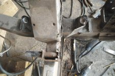
Both sleeves are out. It is interesting that despite the goopy welds from the factory, they seems to have stuck hard in some places and released easily from others. For example, the inside bracket virtually popped off the DS upright, and on the PS if you look closely despite a lot of drilling and pounding with the chisel broke rather than release...

Anyway, for the unfortunate sod who reads this because they are in the same boat:

If yours is stuck like mine, drilling is not worth it, the pin fused to the sleeve throughout -
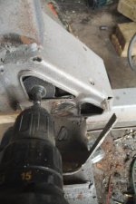
Do have a grinder with grinding and cutting discs
Do buy the arbor for the drill that takes the smaller thinner discs - see if you can find 1.5-2 inch discs, my almost worn out ones got into tight spaces better (see pic).
You are also going to need a pile of small drill bits (the angles will break them constantly), a chisel and regular and 5 pound sledge to break some of the welds
Also, cut and fold out of the way the front bracket, seems to be the only way to get at the rest of it with a grinder.

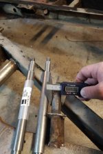
Next I will have to source some tubing, but I am going to wait until the pins get here so I can ensure a tight fit. Is the tube proud of the front and rear brackets? Or, if someone has the ability to measure the total length, that would be helpful,

BTW, the second sleeve removal took just shy of 2 hours, but I have more repair to do on the upright than the first.

Cheers,
Kerry
 

Attachments

  • IMG_20170909_1746378.jpg
    IMG_20170909_1746378.jpg
    76.3 KB · Views: 169
  • IMG_20170909_1657190.jpg
    IMG_20170909_1657190.jpg
    74.7 KB · Views: 180
  • IMG_20170909_1730521.jpg
    IMG_20170909_1730521.jpg
    35.8 KB · Views: 165
Was this the TR you had on the classified?

I presume you will use the removable part of the bracket to get your alignment for reassembly.

I will see if I can get some dimensions off my frame. Front suspension is reassembled so I do not have much room.

David
 
Well done Kerry. Thanks for the pictures too. I may be the poor sod doing this on one side of my spare fame.
The tube length is 8 inches exact. This is confirmed by the side view of the frame unit that is in the Factory Service Manual. My scanner is not working or I'd include a picture. If nobody offers an e-copy of the diagram, I can send you one in the mail.
I use Onlinemetals for tubing and such, fast and not too expensive.
frame pin.jpg
Tom
 
Congrats! As far as I know your the first on the forum to tackle that huge job. Replacing will be easier, but may take as much time getting the alignments perfect. Appreciate the pics as you went!
 
Thanks folks - appreciate the pics.
Alignment shouldn't be too bad given that I left the outer wings intact and I now know the exact tube length.

The challenging part will be welding the inner bracket as you can't pre-weld it to the tube because of space constraints. I may oversize this bracket a bit as the PS took a bit of a beating before releasing and I'd rather be slightly off for size to maintain strength.

David, thanks for the pictures. Notwithstanding the images, I am pretty sure that it is a tube and pin, but I am waiting for the pin to arrive anyway before I move forward, so will have the option to verify when the part gets here.
 
Kerry,
If you are considering a "brake upgrade," I suggest you examine the popular Toyota calipers that fit Triumphs. I have them on both my TR6 and TR3.
What a job, you did good!
 
Thanks Jim - yes, I am looking at the Toyo brakes. once I am a bit further along I will be looking for a pair of tr6 hangers...

Salvador Blue, awesome, I had that color on my first TR3, a 59, bet it looks great on your '56,

Cheers,
Kerry
 
So, my fulcrum pins arrived today. Main learning: do not try and drill, it is one piece of turned metal.

The difference in width between the original is about half a millimeter or less than .03 inch.

The challenge now will be welding, I am going to have to get that pin pretty hot to bond before I can fold the weld pool over to the thin brackets without burning through them. Also, the pin can't go in with the bracket already attached, so there will be space constraints. So get ready for some fat ugly welds... that is, once I get more welding gas...

(David, you were totally right, pin, no tube!)
 

Attachments

  • IMG_20170922_1712366(1).jpg
    IMG_20170922_1712366(1).jpg
    37.2 KB · Views: 143
Last edited:
So it looks like the pins are not in a tube, but rather are stepped in size. I didn't see that coming!
 
Neither did I... especially since I convinced myself there was an "edge" while drilling...

However, if YOU were surprised John, i feel my work here is done, won't be able to top that for the rest of the build :smile:
 
I think everyone has learned from your endeavor! Too bad we can't teach the lesson to your PO that hacked off the ends to begin with...
 
I think everyone has learned from your endeavor! Too bad we can't teach the lesson to your PO that hacked off the ends to begin with...

+1 on both.
Tom
 
Can you use the outer support brackets to help you position the new pins?

Good luck with your welding. Looks like it is going to be tight to get in there.

David
 
Exceptional work, I have always feared one of those breaking. I would have commented earlier, but I was more of a student. Again I am not a fabricator, but would it be possible to make a saddle that would go under and up in one piece U shaped and then welded mostly from the bottom and side and the U saddle for bearing load. Maybe 3/8 thick with a couple of holes and simple design should not be too noticeable, maybe kinda sorta.

steve
 
David, I had hoped to be able to keep both outer mounts as a guide, but this is not going to be possible due to the pin. The transition of thick to thin is at the mount and I can't shoot it straight through. The front mount however is welded on in a way that if I use the small cut off discs, I am confident I can get it back on exactly where it came off.

I have to make some time to play with it, but I have to get some 12 or 14 gauge metal for the bracket and some welding gas too.

Randy, good idea re ratco - looks to me though that they have modified the mount inside the upright, or maybe its just perspective on their website photos...

Steve, not exactly able to visualize what you are suggesting, the load in this area changes as you drive which is why I think it is so reinforced... but if I need to, you can bet there will be extra metal in there as I will always favor function over form.. if I can't get the inside connections how I want them, a plate on the outside of both uprights may be the simplest non-original solution,

thanks,
Kerry
 
Hello Kerry

I was referring to the removable piece that goes directly under the nut. The piece that goes on outside of the control arms.

David
 
Sorry David, got mixed up when I was responding, I was actually confused by Randy's suggestion - however, it taking some of his idea, if I can't get the inner bracket welded securely, I could take a heavy piece of metal and mirror and weld to the out support... anyway, I will try and get tim eon it this weekend and post then,
Cheers,
Kerry
 
Good job Kerry. Lots of time and patience on display here. Keep up the great work.

Cheers
Tush
 
Back
Top