• The Roadster Factory Recovery Fund - Friends, as you may have heard, The Roadster Factory, a respected British Car Parts business in PA, suffered a total loss in a fire on Christmas Day. Read about it, discuss or ask questions >> HERE. The Triumph Register of America is sponsoring a fund raiser to help TRF get back on their feet. If you can help, vist >> their GoFundMe page.
  • Hey there Guest!
    If you enjoy BCF and find our forum a useful resource, if you appreciate not having ads pop up all over the place and you want to ensure we can stay online - Please consider supporting with an "optional" low-cost annual subscription.
    **Upgrade Now**
    (PS: Subscribers don't see this UGLY banner)
Tips
Tips

Smiths RVI Positive Ground Tachometer Bench Test ?

britishrich

Freshman Member
Offline
Hi Folks, First post.....just joined the other day. I did some archive searching and couldn't find what I was looking for.

Update, tach is fixed. See Post #19 for result.

I'm helping a buddy with a '65 Austin Healey 3000 MkIII 6 cyl. My first experience with one. My research tells me it's a BJ8. Tach is dead. I did some troubleshooting and it appears internal to the tach. Car has stock ignition and points, runs fine, but no movement in tach. He has no history of the cars' prior workings.

It had a Pertronix 12VP module in it and I removed it and went back to stock ignition, new points, rotor, condenser, etc. I know the current sensing tach won't play with th Pertronix. No desire to convert tach to voltage sensing. Points set to 0.016" and runs fine.

I removed the tach, cleaned the contacts of the "loop" widget and mating tach contacts. I found and studied those great documents by Mark Olson and David Masucci. I opened the tach and likely have a failed component, but........

I want to test it on the bench to verify it's broken, and verify repair if I can fix it. I was thinking of using a GM dizzy in a vice and hook the tach to a battery(pos gnd), to a 12v test lamp for current loading, then spin the dizzy to see if the tach triggers. Make sense?

Or other suggestions? Either that or ask a friend with a Healey to test it out at his place miles away, but I like my workbench place better.

I have some Jag experience with a fair amount of Lucas knowledge and some Smiths gauge tinkering in the past.

Thanks,
Rich
p.s.
What is the white/black tracer wire for near the coil? It comes from the harness and is pigtailed at a female terminal to another white/black wire about 5" long with a female on it's end. I don't have a complete '65 wiring diagram, only the half that shows the tach and instruments, not the engine bay.
 
Last edited:

Healey Nut

Luke Skywalker
Country flag
Offline
The black /white wire should connect to the side of the dizzy LT terminal then piggy backs with the negative connection on the coil then runs back to the battery isolater switch in the boot (trunk) . Try reversing the direction of the pick up loop on the back of the tach . If all else fails call Nisonger instruments and ask for Peter and see if he can help .
 

rjc157

Jedi Warrior
Country flag
Offline
its probably one of the capasitators that burned out because of the petronics changing the loop would mean converting to neg ground
 
OP
B

britishrich

Freshman Member
Offline
The black /white wire should connect to the side of the dizzy LT terminal then piggy backs with the negative connection on the coil then runs back to the battery isolater switch in the boot (trunk) . Try reversing the direction of the pick up loop on the back of the tach . If all else fails call Nisonger instruments and ask for Peter and see if he can help .

Uh Oh.....I have the white wire from the Ignition switch through the Tach loop to the Negative of the coil. Positive of the coil goes to the dizzy. This is a Pos Gnd car. The car runs fine with it wired this way. It had a Pertronix 12VP in it, a module for Pos Gnd.

I found a BJ8 wiring diagram that shows the Ign wire going to coil SW(= ign SWitch, right?)

When I first was asked to look at this car, the guys said they played around with the tach loop and "added a extra loop" becasue they read that somewhere. Maybe they reversed the loop? Honestly, when I removed the tach from the dash panel I didn't even notice the direction of the loop. I guess it's important for the "eddy current" principle.

Okay, that white/black wire....Now it makes sense. When I used that wire in the harness the engine won't run. A kill switch in the boot? I'm getting a crash course here. Where is the switch exactly? I'm not getting back to the car for a while.

Thanks for the help.

its probably one of the capasitators that burned out because of the petronics changing the loop would mean converting to neg ground

It was a Pos Gnd Pertronix, 12VP, but who knows what they did before I got into this. I can't get back to the car for a while, but would like to test the tach to prove it's condition. I'll try Nisonger for some info. I did read about the cap C2 getting toasted easily.

Thanks.
 

Healey Nut

Luke Skywalker
Country flag
Offline
The polarity of the coil doesnt matter , the direction of the induction loop on the back of the tach does matter . The battery switch if its there is right next to the battery .
 

Keoke

Great Pumpkin
Country flag
Offline
The polarity of the coil doesnt matter:

While the car will generally run if the coil polarity is reversed.
The secondary ignition compnents wil be overstressed and may prematurly fail.
 

Healey Nut

Luke Skywalker
Country flag
Offline
[

While the car will generally run if the coil polarity is reversed.
The secondary ignition compnents wil be overstressed and may prematurly fail.[/QUOTE]

Ground is ground , all you doing is exciting a coil to generate high voltage and interupting a ground to create a spark , how can polarity effect wear and tear on secondary components ?
 

Keoke

Great Pumpkin
Country flag
Offline
Ground is ground , all you doing is exciting a coil to generate high voltage and interupting a ground to create a spark , how can polarity effect wear and tear on secondary components ?

This condition exixts because the voltage required to breakdown the spark plug gap will be higher.
 

Healey Nut

Luke Skywalker
Country flag
Offline
This condition exixts because the voltage required to breakdown the spark plug gap will be higher.[/QUOTE]

The coil can only put out what it puts out it doesnt care what the polarity is and all its looking for is a ground to discharge . Voltage is voltage ground is ground the only thing which can change it is resistance .
 

Keoke

Great Pumpkin
Country flag
Offline
The coil can only put out what it puts out it doesnt care what the polarity is and all its looking for is a ground to discharge . Voltage is voltage ground is ground the only thing which can change it is resistance .

OH ! That may be true in Canada--:highly_amused:

However, go here and read
[h=3]The MGA With An Attitude - Ignition coil polarity[/h]
 

Healey Nut

Luke Skywalker
Country flag
Offline
Ok so if all that science nerd stuff in the link listed is correct then answer this question .
Why do all the articles about converting a car from positive to negative ground never mention changing the coil polarity ??
 

Keoke

Great Pumpkin
Country flag
Offline
Why do all the articles about converting a car from positive to negative ground never mention changing the coil polarity ??

Because:
THE procedure for converting from positive to negative ground insures that the coil polarity is adequately addressed.

IF you remember--For a positive ground car the period coil terminals CB is positive [ EARTH] and SW [ Ignition SW] is negative.-VE

---------------------For a negative ground car these terminals get reversed
 
Last edited:

Bob_Spidell

Yoda
Gold
Country flag
Offline
Ok so if all that science nerd stuff in the link listed is correct then answer this question .
Why do all the articles about converting a car from positive to negative ground never mention changing the coil polarity ??

I'll take a SWAG: because the authors didn't know it should be done. I seem to have misplaced my copy of Norman Nock's Tech Book, but it might be in there. Norman once told me it's necessary to have correct coil polarity for max power and efficiency.
 
Country flag
Offline
Norman told me the same thing and explained that it was the direction of electron flow. You get more power if the flow goes to the center terminal of the spark plug. He said it would run either way but the plug was hotter and more efficient. I switched it (12 years ago) and noticed no difference but why not do it the way it is supposed to be? Simplest job ever on a Healey.
 
OP
B

britishrich

Freshman Member
Offline
I'd have to agree that polarity is a non issue, as long as the case of the coil is not electrically connected to one of the primary terminals.

I thought I read somewhere that some original coils have their cases connected to the "ground", albeit positive or negative. Maybe that's where I was confused earlier in my post.

A coil primary is in fact just a winding that appears statically like a resistor, and it's secondary windings are a much larger number of turns of the windings to create the high voltage.

Rich
 
OP
B

britishrich

Freshman Member
Offline
So I read that article, and I must admit I've never seen any reference like that before. Interesting, and yes, I believe it's likely applicable. What actual effect polarity reversal would have is unknown unless controlled experiments were made and documented. Okay maybe reduce spark plug or CB points life a bit, but in reality how much could it be? The way we use these cars it would probably take years to see the results.

However, either way, I have a running engine with polarity in the "preferred" configuration and will keep it that way.

What I really want to do.........is just test this tach on a bench to prove it's either working or not so I can make some progress.

I'm going to connect it up to a battery through a 12v lamp through a toggle switch that I'll flip rapidly to simulate CB points to see if it has any life at all. I'll set the loop in one direction then the other to see if they had it wrong and was the original problem.

I guess I have a 50-50 shot at it.:rolleye:

HNY
 
OP
B

britishrich

Freshman Member
Offline
Update.....Special thanks to the author of this document, Mark Olson. It was a big help.
https://www.healey6.com/Technical/Calibrate Tach 1.pdf

The tach was diagnosed as defective using my proposed test setup. I connected it using a 12v battery, a halogen test lamp, and a rotary switch. Battery Pos+ to tach case and lamp case, Neg- to tach loop, then through the switch then to the lamp center terminal. Also Neg- to the male terminal at the tach rear as is used on the car, i.e. the Green wire coming from battery power. This powers the internal tach circuitry, and is shown as a GND symbol on the schematic above. I used the test lamp and switch, to simulate the load of the coil through the points, turning the switch rapidly to see if the tach had life. Either direction of the "white" ignition source wire through the tach loop connector resulted in no life of the gauge pointer.

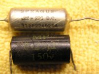
I then disassembled the tach and inspected it. I tested the input coil, meter coil, and a few other components using my test meter. All was good. I then checked solder connections at the 2 transistors, Q1 & Q2 and the capacitor C2. I found C2 had a crack in it's case. I replaced it. It was a 0.25uF 150V un-polarized. I replaced it with a 0.22uF 200V un-polarized electrolytic that I had in a stash of electronic components I had on the shelves.

I reran my bench test and then saw needle movement. I then took the tach back to the car, temporarily installed it and it worked. I then tried reversing the direction of the input wire(white), then no movement. I just wanted to see the results for myself. I then installed it in the dash with the white input wire in the direction as tested good. It worked fine. Fixed. It will need to be checked against a external tach for accuracy and may need further calibration. Another time. At least it works now.

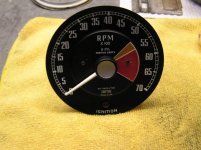
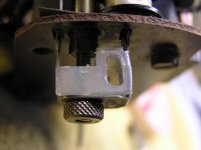
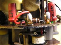
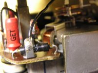
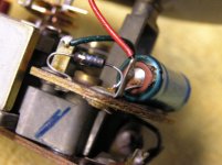
Some pics of the repairs and a few others for future reference..........


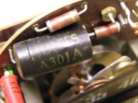
The culprit after removing from the case
P1030001.jpg

Cap C2(black device) showing crack
P1030003.jpg

Replacement & original
P1030012.jpg

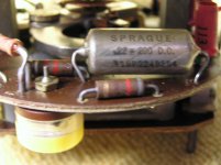
Soldered in
P1030013.jpg


Thanks to all for your guidance with this diagnosis as this is the first Austin Healey I've ever worked on. I learned a few more things about these cars too.

Rich
p.s. more pics next post
 
OP
B

britishrich

Freshman Member
Offline
Tach source loop connector
P1030007.jpg

Transistors Q2(left) & Q1 (right)
Disk Cap C1(0.5uF) is standing up between them.
Also note the red and black wires soldered at 2 terminals,
coming from the loop input coil. (bottom of pic)
P1030006.jpg

Thermistor 55ohm R2 (behind black wire terminal)
P1030008.jpg

Zener diode 6Volt, & Cap C3 100uF(blue can)
P1030004.jpg
 
Similar threads
Thread starter Title Forum Replies Date
58Custom New! Schematic for Smiths RVI tachometer Spridgets 9
RJS TR4/4A Smiths Oil Temp Gauge Triumph 11
S WANTED: Healey BN1 "Smiths" Fuel Gauge (Dead or Alive) Austin Healey Classifieds 3
nichola TR6 Smiths volt gauge needle barely moves Triumph 25
T Wanted Smiths fuel gauge for Mk 1 Bugeye Sprite [FG2530/31] Spridgets Classified 1
RAC68 Calibrate Smiths Tachometer Austin Healey 12
B For Sale Austin Healey 100 Smiths Fuel Gauge, Dual Safety Gauge, Speedometer and Tachometer Austin Healey Classifieds 0
angelfj1 TR2/3/3A Restoring Smiths heaters as fitted to a 1959 Triumph TR-3A Triumph 4
Jim_Gruber Source for Smiths Gauges in UK I believe Spridgets 7
D Smiths Heater rebuild. Restoration & Tools 1
D TR2/3/3A Smiths Heater rebuild. Triumph 2
T TR2/3/3A Smiths Heater Checkout Triumph 7
drambuie Converting a smiths clock to positive ground Austin Healey 12
J Help with Smiths heater. Other British Cars 4
W 100-4 Smiths heater clips Austin Healey 11
G help id this smiths speedo Other Cars 2
K Smiths Electric Temperature Gauge Triumph 7
Tinkerman Jaeger and Smiths Speedometers Triumph 5
luke44 TR2/3/3A TR3 Smiths Heater Plate Triumph 3
RJS Smiths PCV Valve Differences? Triumph 2
M Smiths Fuel Tank Sending Unit Austin Healey 3
R smiths guage problem- need advice Austin Healey 4
M Smiths fuel tank sending unit Triumph 1
C Smiths or Lucas Gauge? Triumph 8
Tinkerman Smiths Heater Lables Triumph 11
angelfj1 New WIKI regarding Smiths Heaters Triumph 0
angelfj1 Link to Smiths Heater Article Now Fixed Triumph 0
angelfj1 How To Restore a Smiths Heater Restoration & Tools 8
angelfj1 Smiths Heater - Completely Restored Triumph 3
angelfj1 Weekend Project- Smiths Heater Restoration Triumph 13
amcboy A little about Smiths gauges... Triumph 31
angelfj1 Smiths heater Parts Triumph 8
tosoutherncars NOS Smiths gauges: Bugeye? Spridgets 4
TR674 Smiths Speedo Triumph 9
B Smiths Dual Guage Repair Spridgets 13
wkilleffer MGB Question about the Smiths temp. gauge- 74 MGB MG 19
coldplugs Be thankful [Re Lucas, Smiths, SU, et al Other British Cars 10
dklawson Needed - 4" Chrome Smiths Bezel Triumph 4
A Brighter Smiths Instrument Bulbs --- Any ideas? Austin Healey 25
S Which Smiths heater in '65 AC Cobra? Other British Cars 5
T T-Series smiths or arnolt heater installation in an MGTD MG 1
Kira Smiths Clocks Pre 1950 Other British Cars 6
G Tacho Smiths RVI2401/00EN needed MG 0
G SMITHS SPEEDOMETERS MG 2
J Smiths Tachometer MG 8
C Need someone to mod my rvi tach for ele ignition Spridgets 2
Z RVI Tach w/ crane ignition? Spridgets 2
Taz RVI tach question Spridgets 11
B Positive-Ground LED Light Strip Austin Healey 8
P Positive to Negative Conversion Austin Healey 1

Similar threads

Top