• Hi Guest!
    You can help ensure that British Car Forum (BCF) continues to provide a great place to engage in the British car hobby! If you find BCF a beneficial community, please consider supporting our efforts with a subscription.

    There are some perks with a member upgrade!
    **Upgrade Now**
    (PS: Subscribers don't see this gawd-aweful banner
Tips
Tips

Rough Running 99 XJ8 after Overheating

I took the timing cover off the engine removed for the photo in the previous post and to get a look at how the adjustable cam timing works.

In the photo below, you can see that the braket that supplies the oil on the left bank, as viewed from the fromt, is held on with 3 bolts woth 10mm heads.
 

Attachments

  • 29030.jpg
    29030.jpg
    65.4 KB · Views: 206
Opps, wrong photo, the photo above is the r/h bank with the bracket removed. this provides access to the 10mm allen head bolt for the intake cam.

The photo below shows the bracket.
 

Attachments

  • 29031.jpg
    29031.jpg
    58.1 KB · Views: 202
The article said that you had to remove the radiator for clearance toget a puller to remove the harmonic balancer. I had a local machine shop make a 1/2" thick steel plate with 31/32" diameter hole to use with a universal pulley puller from Autozone. With it, I did not need to remove the radiator

In the photo below, you can see the puller, disk, balancer and the split cone. After the bolt that secures the balancer is removed, the balancer tool was installed using two M8 1.25 bolts about 1 1/2" long Balancer came right off.
 

Attachments

  • 29128.jpg
    29128.jpg
    60.3 KB · Views: 196
Diameter of the plate is 3.5". The slots could have been made 3/4" long and 5/16" wide. Place the slots at the edge of the disk. I initially had oval slots and had to cut the outer edge away to fit the bolts. I did not place the slots far enough away from the center.

With the balancer removed, and the bolts that secured the timing cover removed, there was enough room to pull the cover forward to get clearance to remove the bracket from each intake cam gear which gave access to the 10mm Allen Head bolt securing the gear to the cam. The photo below shows the left bank with the bracket removed. Clearance is tight with the top radiator hose and the timinh cover. you might want to drain the radiator and remove the upper hose, but it can be done, as I did with out removing the top hose.
 

Attachments

  • 29129.jpg
    29129.jpg
    64.8 KB · Views: 196
Scroll back up to one of the photos of the engine that I removed. The exhaust cam gear has 4 holes. The holes allow a wrench from the cam chain tool kit to fit and hold the gear while the bolts are loostened. The wrench had a 1/2 inch square to allow a 1/2 inch drive breaker bar to be used with the wrench. You can see this in the photo below.
 

Attachments

  • 29130.jpg
    29130.jpg
    54.5 KB · Views: 191
After buttoning everything up, I ran the car. It was hard to start, but the roughness from before adjusting the cams was gone. I still get "restricted performance","stability control failure" and now low coolant, but the coolant level seems fine.

There were five codes:

P0102 - Mass Air Flow Sensor Circuit Low Frequency
P0112 - Intake Air Temperature [IAT] Sensor Circuit Low Voltage
P0336 - Crankshaft Sensor Circuit A Range/Performance
P1000 - The Jag Lovers.Org list of OBD-II Codes stops at Po846 and continues at P1001. I will check the Jag XJ8 Supplementary DVD to see if it lists a description.
P1648 - Knock Sensor Input Chip.

I ran a compression test. It revealed the following:

1 - R/H Front 170
2 - R/H Second from Front 170
3 - R/H Third from Front 165
4 - R/H Rear 175
5 - L/H Rear 126
6 - L/H Third From Front 126
7 - L/H Second from Front 122
8 - L/H Front 122

Any Ideas????
 
Michael, What an informative forum, you have the patience of a Saint.
You are making a tensioner replacement seem like child's play.
Thanks for all the great pictures and putting them on the BCF.
I hate you seem to have a problem on the left bank, might get lucky and just need a torque. Let us know.

Thank you, Wayne
 
The low compression values on the left bank made no sense.

I went back and pulled the left valve cover again. What I saw was that the intake cam flat was about a half a tooth off.

The only thing I could figure was that the spring loaded chain tentioner depressed slightly when the bolt for the cam sprocket was tightened. I used one of the T-shaped wedges (which are made out of aluminum) to depress the cam chain tentioner before retightening the intake cam spocket bolt.

So, even thoughholding the exhaust cam sproket with the special pin wrench, it must be possible to depress the spring loaded tentioner so that both cams will not stay with the flats aligned.
 

Attachments

  • 29346.jpg
    29346.jpg
    61.9 KB · Views: 166
Take a few photos of the serpentine belt routing before removing the belt in order to remove the harmonic balancer. There is no decal showing the routing and I could not find an illustration on the service DVD.
 

Attachments

  • 29348.jpg
    29348.jpg
    49.1 KB · Views: 182
Tahe a few photos of the belt routing because there is no decal under hood that I found showing the routing.
 

Attachments

  • 29349.jpg
    29349.jpg
    53.2 KB · Views: 172
Here is the Harmonic Balancer with the puller installed

You have to pull the balancer to get the bracket for the variable cam timing off to get at the intake cam sprocket bolt.

After repeating all the steps described above, left bank compression was:

178 l/h front
172 2nd from l/h front
178 3rd from l/h front
170 l/h rear.

I am still having a low oil pressure light and restricted performance and stability control failure warning.
 

Attachments

  • 29350.jpg
    29350.jpg
    63 KB · Views: 176
Michael J. Hope you have it all sorted out by now. Did you do a hard reset or was the faults something a little weird???

Wayne
 
I don't have it sorted out yet.

By "Hard Reset" I am assuming you mean to disconnect the battery to reset the ECM?

Whaty I get is "Restricted Performance" and "Sability Control Failure"

I have had both show up on the dash before and had to go clean each ground and remove and clean each connector.

Is there something specific I can look at as a possible source?
 
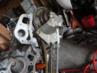
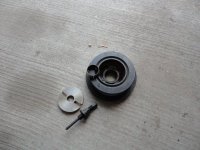
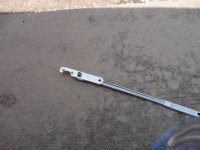
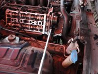
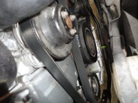
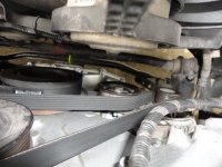
The oil pressure problem was resolved by putting the oil pump from the original engine on the rebuilt engine. There was a lot of trash on the oil inlet screen for the pick-up tube. XJ8 Oil Pump.jpg


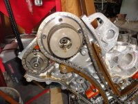
Original pump in the left. The pump with the problem is more sophisticated with oil spray nozzles for the timing chains, but could not be used with the original pick-up. The oil pan had a lot of silver gunk which, if you have ever used Never-Seize, lead me to think that was used as the assembly lube on this rebuilt engine.

I am still having Restricted Performance with the following codes:

P1648 - Knock Sensor Input Chip.

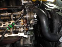
Both sensors were replaced. I have cleaned the connectors located on both sides of the thermostat tower multiple times. Occasionally the code will clear, but comes back after a short run.

P0336 - Crankshaft Position Sensor Circuit A Range/Performance

I have disconnected and cleaned the sensor connector several times and finally replaced the sensor. Still have the code.

P1000 - There is not a listing for this code in the Generic and Jaguar specific OBD-II Diagnostic Trouble Codes list from Jag-Lovers. It is also not listed in the Actron Pocket Scan Code Reader code list.
Any Idea what the P1000 code is?

P1637 - CAN Link ECM/ABS Control Module Circuit/Network Any idea how to check this one?

And P1648 at the end of the five codes displayed.

I had gotten another ECM with the exact same part number on it, but have learned that the key has a chip that must be programmed with the ECM or the car will not start.

Other than trailer the car to a Jag dealer, any suggestions?
 
I finally broke down, loaded the car on a tilt bed and had it towed to the Jag dealer an hour and ten minutes away. They programmed the replacement ECM. The technician changed six relays. The brown colored relays he a problem with contacts burning. The replacements are black in color, manufactured by Ford. The technician also said that he thought that the rough running might be caused by not bottoming the variable valve timing pistons. I had to order the special wrench to make the adjustment. The technician told me that the adjustment could be made using needle nose pliers, but I could not get the pliers to work. Here is the wrench that is needed.
 

Attachments

  • Variable Cam Wrench.jpg
    Variable Cam Wrench.jpg
    49.6 KB · Views: 65
On the variable valve timed cars, it is necessary to pull the Harmonic Balancer so that the timing chain cover can be removed. This is necessary in order to remove the oil solenoids and housing.
 

Attachments

  • Cam Oil Feed.jpg
    Cam Oil Feed.jpg
    56.7 KB · Views: 61
In the photo above, the cam timing oil feed seen on the right side of the engine is attached with three bolts with 10mm heads, while the housing on the left side has two bolts and one nut that attaches to a stud.
 
With the wrench installed in the front end of the Intake Variable Timing Piston, rotating the wrench to the left or right will cause about 30 degrees of variation. What you want to do is rotate the wrench to the left side of the car and then check the cam flats for alignment with the pin installed at the flex plate as can be seen earlier in this thread. If not aligned, install the cam flat alignment tool, loosen the 10 mm Allen head bolt for the Intake cam and make tighten the cam alignment tool to lock the flats in the proper position. Make sure that the wrench for the piston is still bottomed to the left before the tightening the 10 mm Allen Head Bolt.
 
Back
Top