-
 Hi Guest!
If you appreciate British Car Forum and our 25 years of supporting British car enthusiasts with technical and anicdotal information, collected from our thousands of great members, please support us with a low-cost subscription. You can become a supporting member for less than the dues of most car clubs.
There are some perks with a member upgrade!**Upgrade Now**
(PS: Subscribers don't see this gawd-aweful banner

Tips
- We have a special forum called "Member Articles" where you can submit actual articles for consideration for publication. Learn More
- Don't have an Avatar? If not, your avatar will default to the 1st character in your username. Go into "Account Details" to change your Avatar.
- Some basic forum navigation info: click
Hey - did you know if you click on the title of a thread it will take you to the first unread post since you last visited that thread?
- Hey Guest - Is your British Car Club in our Clubs database? If not, send me a PM - Basil

- Looking for a local club? Click the "Clubs" tab above and browse hundreds of clubs world-wide.
- Add Android or iPhone APP: click
- Did you know - any picture or video you add in your posts in any marque-specific forum will also get added to the Media Gallery automatically.
- A few more tips about posting and replying: click
- Hey there Guest - be sure to keep your profile page up to date with interesting info about yourself: learn more
- More tips and tricks on Posting and Replying: click
 STOP!! Never post your email address in open forums. Bots can "harvest" your email! If you must share your email use a Private Message or use the
  smilie in place of the real @
- Want to mention another member in a post & get their attention? WATCH THIS

- So, you created a "Group" here at BCF and would like to invite other members to join? Watch this!
- Hey Guest - A post a day keeps Basil from visiting you in the small hours and putting a bat up your nightdress!
- Hey Guest - do you know of an upcoming British car event?
 Pretty Please - add it to our Events forum(s) and add to the calendar! >> Here's How <<
- Hey Guest - you be stylin'
Change the look and feel of the forum to fit your taste. Check it out
- If you run across an inappropriate post, for example a post that breaks our rules or looks like it might be spam, you can report the post to the moderators: Learn More
- If you would like to try some different "looks" or styles for the site, scroll to the very bottom, on the left and click the Style Selector.
You are using an out of date browser. It may not display this or other websites correctly.
You should upgrade or use an alternative browser.
You should upgrade or use an alternative browser.
PCV and oil leaks
- Thread starter mgtf328
- Start date
Steve,
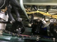
Sorry, I've probably missed something. Where's the PCV located on the image above? I can't see it.
Is that 5" or 0.5" under hard acceleration? I think 5" may be a bit on the high side. If it is 5" I would say the valve isn't reaching the "sonic flow" condition because the valve orifice is a bit on the large side. It would be interesting to try a smaller valve rather than a larger one.
I'm proposing to use a manometer instead of a gauge because all of the gauges I've seen here measure 0 - 30" Hg. I don't expect cheap gauges to be accurate enough to measure 1" Hg reliably. Anyway why spend 30 bucks when I can make a manometer out of a bit of plastic tubing!
On another point, I'm not claiming this is rocket science. When you search the web you find MANY technical papers on this subject by University's, Ford, Caterpillar, Toyota, etc. and you start to wonder why so much money has been spent on it. From my reading of the few I have downloaded, drawing a vacuum on the crankcase will affect oil distribution and engine performance. I guess the manufacturer's are trying to avoid warranty claims by funding this research!
Most papers I've seen agree that the depression isn't arbitrary. They're trying to avoid sucking oil/air/dirt through engine seals or cavitation/slip in the pump.
To conclude, I agree, apart from the fact that it interests old retired engineers with little else to do (Me!) most of us are probably trying this to prevent oil leaks. After all it's cheaper than pulling the engine out. As you get older you have to work smarter, that engine is heavy!
AJ
ps I wouldn't dream of leave my Porsche idling with the oil cap off. Why would you do this?
D
Deleted member 21878
Guest
Guest
Offline
steve
are you thinking you will not need an oil catch can in the line?
once it cools down, i will have to test my set up on the road and see if my reading changes.
only other thing i did was put a small mark on my valve. just a quick check to see if it moved while driving.
are you thinking you will not need an oil catch can in the line?
once it cools down, i will have to test my set up on the road and see if my reading changes.
only other thing i did was put a small mark on my valve. just a quick check to see if it moved while driving.
D
Deleted member 21878
Guest
Guest
Offline
AJ
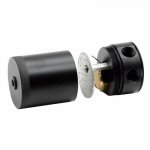
if you look close i think Steve has his filter and air valve hooked to his side pipe, which is in front of his Valve cover T. his valve cover T has his connection for his gauge on the laft side and his PCV valve on the right side which goes to his manifold.
if you look close i think Steve has his filter and air valve hooked to his side pipe, which is in front of his Valve cover T. his valve cover T has his connection for his gauge on the laft side and his PCV valve on the right side which goes to his manifold.
Offline
AJ - apologies for the unclear photo; my PCV valve is per the pic in Post #5 above. Yes, it's 0.5" under hard acceleration.
DD - later today, I'll be working on making an orofice to match the flow on the brass valve. My valve is fairly stiff, so I wouldn't be worrying about it shifting while driving.
DD - later today, I'll be working on making an orofice to match the flow on the brass valve. My valve is fairly stiff, so I wouldn't be worrying about it shifting while driving.
Congratulations Steve, I think you've cracked it.
How will you size the orifice to match the valve flow, trial and error? When I did my MG I used a short length of steel rod with a 1.7mm hole drilled through it and I rammed it into the pipe before the PCV
I tried fitting a catch tank between my breather T and air filter and it pressurised the rocker box and the gasket leaked. See image attached. I think the sintered metal filter in the head is too fine and there wasn't enough suction to draw the gases through from the crankcase. It may work better attached to the inlet manifold.
If you could summarise what you did when you finish I think we can draw a thick line under this post and PCV valves.
If I order one of those valves from NAPA tomorrow, do you think I might get by next spring!!
Thanks guys.
AJ

Offline
AJ - I've never felt the need for a catch tank. My engine has <7000 miles since the rebuild. Very little oil seen in the PCV valve after running. Will keep checking.
Am using a 1/2" electrical panel hole plug. For the jet, 7/64" hole resulted in almost no vacuum. Settled on 3/32" hogged out slightly to give: 1.5" Hg idle or downhill; 1" cruise; 0.5" hard acceleration.


I'm going to trim the edges and enclose it in the 5/8" hose from the side pipe to the rear air cleaner.
DD - what did you use to plug the left side of the T?
Am using a 1/2" electrical panel hole plug. For the jet, 7/64" hole resulted in almost no vacuum. Settled on 3/32" hogged out slightly to give: 1.5" Hg idle or downhill; 1" cruise; 0.5" hard acceleration.

I'm going to trim the edges and enclose it in the 5/8" hose from the side pipe to the rear air cleaner.
DD - what did you use to plug the left side of the T?
D
Deleted member 21878
Guest
Guest
Offline
steve
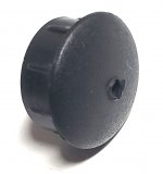
i got rubber stoppers from Lowes. they were in one of the drawers in the bolt aisle.
i got rubber stoppers from Lowes. they were in one of the drawers in the bolt aisle.
D
Deleted member 21878
Guest
Guest
Offline
Offline
Steve
much cleaner set up.
you were asking about the plug i used. you could just put a rubber cap over your fitting to seal that side off. then it would be easy to hookup the gauge anytime.
same idea as here just up on top.
Good idea about the cap. I need to replace my lo-rent plastic barb with a cool brass barb like yours.
Offline
steve
i got rubber stoppers from Lowes. they were in one of the drawers in the bolt aisle.
This looks clean:
Bob_Spidell
Yoda
Offline
I put something like that in the hole in the bell housing for the release bearing fork. I think it's there for installing/extracting the tapered pin on the fork, but figured it would allow dust into the bell housing on a dirt road. I wasn't sure of the size when I was in Lowe's, so now I have a collection of them


