• Hey there Guest!
    If you enjoy BCF and find our forum a useful resource, if you appreciate not having ads pop up all over the place and you want to ensure we can stay online - Please consider supporting with an "optional" low-cost annual subscription.
    **Upgrade Now**
    (PS: Subscribers don't see this UGLY banner)
Tips
Tips

PCV and oil leaks

steveg

Yoda
Gold
Country flag
Offline
From MEWagner's "PCV Valve Shootout" page, summary:

>>>
The most basic metric of evaluating a PCV valve’s performance is how effectively it evacuates the crankcase of blowby under a variety of driving conditions. When a PCV valve flows the proper amount of air, it will evacuate blowby from the crankcase and draw fresh air into the crankcase through the valve cover breather During this condition, a slight vacuum is present in the crankcase. This slight vacuum is also helpful in preventing oil leaks.​
When the engine produces more blowby than the PCV valve can handle, the blowby gasses find their way out through the valve cover breather. In this condition, the crankcase is under a slight amount of pressure, and no fresh air is drawn into the crankcase. This pressure is detrimental for oil leaks, but also indicates a more serious problem is present, the crankcase is not being properly evacuated. The acids and moisture present in the blowby are not being cleaned from your crankcase under this condition.
 
D

Deleted member 21878

Guest
Guest
Offline
AJ
if you want someone with "little knowledge" i am your man.

as i read it:
first a little vacuum expands the seals and rings in the cylinder. thus cutting back on oil leaks and blow-by. i guess if it cuts back on blow-by it has to increase compression and maybe add a little power... but not thinking that is a noticable amount.
second, the addition of fresh air in to the crankcase helps get rid of harmfull gasses and moisture. this helps with sludge and rust.
third, pulling the gasses back thru the engine help with pollution.
Last, the addition of the air filter allows for any positive pressure to escape. have not noticed that on my car.

the trick is getting a little vacuum without too much. too much vacuum pulls in dust and dirt thru the seals. Not a good thing obviously. And maybe could pull oil from the rear main bearing. i don't believe a small amount of vacuum will do that. in my case, with the rear seal kit, i hope it just expands the seal.

i use a valve because, with just the filter, i don't feel i keep enough vacuum. again i was shooting for the 1" HG. the valve makes it easy to adjust. i think you used a fitting on your MG trying for the same thing.

if you are asking if the PCV is necc? well no. i don't think so. these engines ran a long time without them and should continue to do so if maintained properly. i thought it a fun project and if it helps on the pollution side, that is a plus.

Steve,
i think going thru the front tappet cover is probably the best idea. it seems logical that the further you are from the valve cover / vacuum port, the better.
 

steveg

Yoda
Gold
Country flag
Offline
...the trick is getting a little vacuum without too much...

I think keeping a little crankcase vacuum throughout the operating range is what its all about. The closer we can get to that the better.

Proposed science project: attach a vaccum gauge by a long hose to a tee in the side pipe; With the vacuum gauge in the passenger compartment, take a typical drive and see how the vacuum varies. Do this with various small-engine PCVs until one is found giving a small amount of vacuum under almost all driving conditions.
 
D

Deleted member 21878

Guest
Guest
Offline
Steve
when i tested my set up, i tried it with the engine idling and at higher revs.... 2000 rpm, 3000 rpm, etc. i also watch the vac gauge during accel and decel. (the time of highest vacuum i believe) in all cases my vac gauge never moved from the 1" HG. i took this as a sign my PCV valve was working as it should. controlling the vacuum is all situations.

i was interested in the article from Wagner where they talked about idling at 1" HG and running at 3" HG. that was something i had not read before. i wondered if they explanied that part to you.
 

steveg

Yoda
Gold
Country flag
Offline
... i wondered if they explanied that part to you.

DD - Just had a general conversation.

Just wanted to clarify - were your vacuum readings from the crankcase side of the PCV (crankcase vacuum as opposed to manifold vacuum)? Was it while driving or stationary revving of the engine?

If you drove your car and at all times had 1 - 3" HG crankcase vacuum (as opposed to positive pressure), with a vent to the crankcase, it sounds like your PCV is working as it should. If all that's the case, I'd like to know the PN of it so I could try it as well.
 
D

Deleted member 21878

Guest
Guest
Offline
Steve
all of the readings above were from the crankcase side. the manifold side varies with the changes in Accel, decel, idle etc. as you would expect.

at first i tested my vaccum from the dipstick tube. then i wondered how good my seal was at the dipstick. So moved my gauge over to the top of the side vent pipe. Keep in mind i have my valve cover T plugged on that side so i can pull the pipe and not have a vacuum leak. i got the same reading so my dipstick must be sealing fine.

all of my testing was done revving the engine and not driving. but revving the engine and backing off, my gauge never changed from 1" of HG. the needle on the gauge never even wiggled. it was rock steady. that is why i was interested in that 3" number and their thinking on that. i had not read that anywhere before.

i used a NAPA PCV valve. According to the guy at NAPA it the cross reference to the PV770 that was talked about on this forum. the part number at NAPA was 29228.

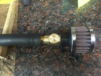
Note: when i just added the air filter i was not showing any vacuum on the gauge. i then added a small brass fitting in the line to cut back on the air flow while measuring the vacuum from the dipstick tube. at first i believe it was 4-5" HG. i would then take out the fitting, drill it out a little and then test again. i got it pretty close to the 1"HG i was shooting for.

fullsizeoutput_2d4.jpg

next day i was in HF and i saw the valve. seeing it was for a paint gun, assumed it would be air tight. i switched to the valve to dial in the amount of air being pulled thru the filter.
IMG_0774.jpg

eventually i changed the hose setup around so i could move the filter behind the brace to get it out of the way. that is the picture in my first post here.

when i shut the car off, i can hear air being sucked thru the valve for about 2 seconds. the only noticeable difference i have found. my idle on the car did not change. i did adjust my front carb a little richer just because all of my air is going in to that front manifold. (tri-carb) i think i set the seat about .005 lower. so far my plugs 1-4 look the same and did not look lean on my plug test runs. plugs 5/6 still show a little more carbon even though the valve cover does not vent there anymore.

i say my idle did not change... i have never gotten my car to idle at a consistent rpm even before i added the PCV. it is very smooth but lowers when the car gets hotter.... hey that is a subject for another thread.
 
D

Deleted member 21878

Guest
Guest
Offline
i understand.
let me see what i can draw or show with pictures.
 
D

Deleted member 21878

Guest
Guest
Offline
first of all AJ, sorry if we hijacked this thread. hope your questions got answered.

steve broke this down in to top of engine and side of engine.

top of engine or vacuum side.
fullsizeoutput_371.jpg

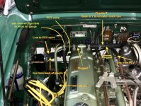
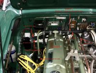
you can see i put a plastic T in the line from the valve cover to the carb. i could have used an elbow or gotten a U shaped hose to run directly to my oil catch can. i chose the current setup because it looks closest to the original. the plastic T has a rubber plug glued in the side with the hose to the carb. the hose to the Carb gives it a little more stiffness. From the back of the T, the line wraps around behind the valve cover and to my oil catch can. then comes out of the oil catch can with 5/8 hose to the PCV valve. then on to the copper line i have going to my vac port on the front manifold.

Note: the left side of the green metal T on top of the valve cover is also plugged with a rubber plug. did not want to pull air up the side pipe. picked both rubber plugs up at Lowes.

shows rubber plug in valve cover T. forget hose on right side of T, it was changed like pic above with plastic T in it.
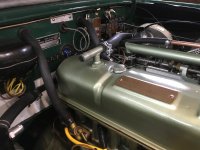
IMG_0763.jpg

side cover or air inlet side:
IMG_0777A copy.jpg
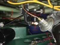
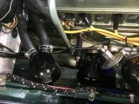
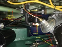
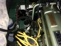
you can see my air filter at the bottom right. i moved it there to get it out of the way plus i was afraid it would shake too much with the weight. when i ran it thru the hole in the brace, i made a little bracket to hold it steady. also holds the valve steady. the brass has a little weight to it. i did use a number of hose clamps. i had a few laying around from a MG car kit.

like i said before, the filter alone gave me no reading on the vacuum gauge which is why i added the valve. i think it was 3 bucks at HF. i also put a screw in the oil cap to seal that vent hole and sealed the dipstick with a little seal i made and a couple o-rings below it.

once together i pulled the top of the side pipe out of the hose (first pic left side of metal T on valve cover) connecting the gauge there. i felt connecting it to the top of the side pipe gave me a more real reading figuring my dipstick might leak a little. but you can also check the vacuum at the dipstick tube.

then i just adjusted my valve to give me just under 1" HG on my gauge. pulled the gauge off and connected the top of the side pipe back to the hose at the metal valve cover T. of course i did a little testing in there first.

hope this answers all questions. if not i can try again. i get in too big a hurry trying to explain things... i know.
 
D

Deleted member 21878

Guest
Guest
Offline
steve
yellow is easier to see but could not figure out how to get rid of the red. so both show up. sorry.

hope it helps.

fullsizeoutput_3b8.jpg

fullsizeoutput_386.jpg
 

steveg

Yoda
Gold
Country flag
Offline
I ran a road test with this setup. No venting. Steady readings.
CV727C (3.3L, 199 cu in) - 5 - 9 in Hg
PV770 (3.8L 231 cu in) - 1.5 - 3 in Hg.

I had been running the 727 for months with no ill effects.

The 770 installation increased the idle from 700 to 1100 rpms (leaning out intake?). It started off around 14 in Hg then settled in at around 3. After a few miles the car suddenly started smoking like a WW2 destroyer or Trabant. Evidently it was pulling oil up the side pipe and the clear tube was full of oil, somehow.

Will try a longer drive with the 727 in next day or two to see if my setup caused that or the 770.

With the stock road draft tube in place, gauge was neutral under all conditions - evidently minimal blowby.

With the dipstick removed, 727 went to around 1" Hg. My dipstick sealed same without o-rings as with o-rings.

Have vent filter and 5/8" barb fitting on order and will experiment either with adjustable valve or orofices.

screenshot.1869.jpg
screenshot.1870.jpg
 
D

Deleted member 21878

Guest
Guest
Offline
steve
can't see your gauge.. what does it read? was it steady or did it vary?
 

steveg

Yoda
Gold
Country flag
Offline
DD - the yellow is much better!

When you hook up your gauge, are you unplugging the left side of the valve cover "T" and plugging your gauge in there?

My car wasn't running when I took the gauge picture. My gauge is old and at rest shows 1" Hg. The readings above are adjusted for that.

All readings were rock steady, not vibrating, but would slowly vary over the ranges in the post above. Not during steady driving, but when changing to deceleration or under acceleration or idling at a stop.
 
OP
M

mgtf328

Jedi Hopeful
Country flag
Offline
DD, I found the following references which I think more or less confirms your design and the target of 1" HG = 4KPa.

[FONT=Verdana,Arial,Tahoma,Calibri,Geneva,sans-serif]"Crankcase pressure control in an internal combustion engine: GT-Power simulation Marco Fogliarino University of Windsor"

[FONT=Verdana,Arial,Tahoma,Calibri,Geneva,sans-serif]"Performance study of a diaphragm type crankcase pressure control valve Sh. Alaviyoun1, M.A. Ehteram"

I download them from Google.

According to the Papers, the aim is to size the valve "orifices" so that the valve "chokes" i.e. flow reaches sonic conditions at a defined pressure differential. At this point the flow ceases to increase with rising differential. This maintains a constant pressure in the sump at the design objective.
They recommend not exceeding 4kPa = 1" HG to avoid upsetting oil flow and damaging seals.
It looks like you hit on a valve which achieves this. Wish you could get them over here but it doesn't look much different from the one I put on my MG so I'll try that.
I think the idea of fitting a restrictor in the line to the valve will achieve the same effect if the valve proves to be too big. So it will be a trial and error process to get it right.
I may change the blanked off tappet side cover to a vented one for the fresh air intake should for convenience. I could also use this "tapping", to set up an oil filled U tube to measure the pressure in the sump. I've not found a gauge that measures less than up to 30" Hg at a reasonable price, I think that's to big to measure 1" Hg. I'll use oil in the U tube (plastic pipe) to avoid sucking water into the sump if the pressures' to big!
A winter job!
Thanks for your help I'll let you know how I get on.
AJ [/FONT][SUB][SUP]
[/SUP][/SUB]
[/FONT]
 
D

Deleted member 21878

Guest
Guest
Offline
Steve
no the left side of my valve cover T is plugged. i wiggle out the side pipe from the hose and hook my gauge to the pipe. pic below shows the vac gauge hooked at the bottom of the pipe right to the plastic T. it was taken earlier in the process.

obviously i got good advice on not pulling the vacuum from the side cover if you got oil thru the line.

i am surprised you got the much oil all the way up there with just 1-3" HG. Or did you get more during decel, idle?

looks interesting to me that the valve for the larger engine produced less vacuum. guess the larger engine is set up to allow more volume?

question:
Are PCV's designed specifically for engine to achieve an exact vacuum or just to get it close? is it designed to allow a certain vacuum based on the amount of air allowed in to the engine?

even new, every model engine is not the same. i know these PCV valves were not designed for our cars. but think about even newer cars. they have a PCV valve designed for them when they are new. as the engine wears it has more blow by and worn seals, especially in the 70's and 80's. yet they use the same PCV valve if they need replacing... for that reason i wondered if the different PCV's made a lot of difference. or do you select one and just balance with the air allowed in as we are talking about here? of course then we get back to volume... wow above my pay grade for sure.

AJ,
i think you can put restrictor in the line, drill it to get the right vacuum. i would have left my 1/8" barb fitting in if i had not found a cheap valve. did i mention i was cheap? Keep in mind my PCV valve alone does not give me the 1" HG. it takes the air intake plus the restrictor (my case air valve) to get the 1" HG.

you bring up a good point i was curious about. is it better to put the restrictor/air valve on the PCV valve side or on the air intake side? i would think it would be better on the air intake side. Will putting it on the PCV valve side or vacuum side cause a higher vacuum at the PCV valve than in the actual engine? possibly keeping the PCV valve from operating properly?

thanks for the reference on the articles. please let me know how it turns out.

here is a pic i had of the set up before using the air valve. the restrictor fitting is below the filter. i did not like the filter sitting there and it wiggled too much for me. the hose you see coming at you connects from the plastic T to my vacuum gauge. early testing phase.
fullsizeoutput_3b9.jpg
 
OP
M

mgtf328

Jedi Hopeful
Country flag
Offline
To answer your question. From reading the papers I concluded that the valve is sized for the engine. The object is to keep a constant 1"Hg depression in the crankcase. The valve is sized for the engine so that as the depression increases between the intake and the crankcase the flow increases through the valve and the pressure in the crankcase drops until "Sonic" conditions are reached (Google "sonic flow") in the PCV valve. At sonic conditions a further increase in pressure drop across the valve will not result in an increase in flow through the valve so the curve of pressure drop against flow flattens out and the 1" Hg is maintained.

No I didn't mean to say I got oil in the line. I'm thinking of fitting both tappet covers with a "breather" cover. I would use one breather for the PCV and the other for the filter. I could also use the second one as a temporary tapping point for a U Tube/manometer pressure gauge which would more accurately measure the pressure. I would fill the U tube with oil rather than water in case the pressure in the crankcase sucked the oil into the crankcase.
Here's a link to the site I got the ideas from when I did my MG. If you troll down you will see a post by Declan Burns in which he attaches a sketch showing how he measured the depression in his MG TD. I fitted the restrictor before the PCV as I was afraid it might be sucked into the intake!

[FONT=Verdana,Arial,Tahoma,Calibri,Geneva,sans-serif]https://mg-cars.org.uk/cgi-bin/or17?runprog=mgbbs&access=71427636401086&mode=archiveth&subject=8&subjectar=8&thread=2014051414162825566
[/FONT]
AJ
 

steveg

Yoda
Gold
Country flag
Offline
AJ - it was me that got oil in the line and started burning oil - that was with the 770 3.8 liter valve.

IMO the ideal would be to find a valve for a 3 liter engine. This comes close: CV727C (3.3L, 199 cu in)

DD - today my filter is coming in, so will redo the setup with the filter on the top of the side pipe (disconnected from T). Will plug the vacuum gauge into the left side of the T and try both PCV valves again.

AJ - can't you just get a vacuum gauge (here's a Gunson), or am I not understanding?:

screenshot.1872.jpg
 
D

Deleted member 8987

Guest
Guest
Offline
While some claim it's rocket science...it ain't. To come up with a number for vacuum.....funny. All it is supposed to do is scavenge crankcase gasses and run them back through the engine. POSITIVE crankcase ventilation was just that....ventilation.
To have some specific vacuum number was not part of the plan. Especially not enough to suck air in past seals.

Ford Motor Company several years ago came out with a high-flow PCV valve for high mileage, high blowby engines. Obviously, some arbitrary vacuum number was no longer in play.

Ventilation. As in, filtered air (oil fill cap or venturi side of air cleaner) through engine to PCV.

I know what happens when you put a PCV onto an engine/carb setup never designed for it. Instant vacuum leak, richen up the carb(s) to compensate, more fuel, more emissions.

If someone is adding PCV components to stop an oil leak......something else is wrong. Clapped out engine, or someone plugged the factory vents.

Wait until you get into newer cars that specify vacuum in the crankcase....and the car will barely idle with the oil fill cap off. But those are FAR newer than the ones we are currently discussing.
 

steveg

Yoda
Gold
Country flag
Offline
My test setup with the CV727C PCV valve. Was able to adjust it to give 1" Hg cruising; 0.5" hard acceleration; 1.5" at idle. I'm satisfied with this setting. (Gauge is old, pointer rests at 2" mark)
No change in idle or AFR with 727.

screenshot.1873.jpg
screenshot.1874.jpg
screenshot.1875.jpg
 
Last edited:
Similar threads
Thread starter Title Forum Replies Date
L Oil in PCV valve Spridgets 30
R TR4/4A TR4A Excessive oil consumption-PCV valve or ?? Triumph 9
abarth69 1275 PCV valve and oil leak Spridgets 7
jehuie PCV valve explanation? British Motor Corp 5
D MGB PCV and charcoal canisters MG 0
steveg TR6 Adding a PCV valve Triumph 5
D Tri-carb PCV valve Austin Healey 61
steveg PCV Valves - testing Austin Healey 8
C TR4/4A PCV System Triumph 4
C TR4/4A PCV Valve Triumph 0
S TR4/4A PCV valve Triumph 12
ttrotter PCV VALVE [or not!] 67 BJ8 Austin Healey 36
KVH TR4/4A pcv valve plus breather tube? Triumph 24
N TR4/4A PCV hoses Triumph 5
vette PCV Valve, Jumping in With Both Feet Austin Healey 17
D PCV Valve guts Spridgets 8
D PCV System- What adjustments to make after fitting Austin Healey 18
J TR2/3/3A Tr3-eary 4s, draft tube and /or PCV valve?? Triumph 13
TR4A_IRS Best adhesive for PCV diaphragm? Triumph 5
Jer Too Low of idle cause PCV to malfunction ? Spridgets 1
Boink "Tuning" or dialing-in the pancake-style PCV valve Spridgets 9
Boink PCV set-ups... can we discuss? Spridgets 18
P E Type V12 PCV & Smog systems Jaguar 8
R TR4/4A Tr4a rpm, with or w/o PCV Triumph 3
T Do I need a PCV assembly or can I just vent ? Triumph 7
R pcv valve for 1500 midget? Spridgets 18
doates Smith's PCV Triumph 1
Rut PCV installation results Spridgets 40
T Use PCV or just cap and vent? Triumph 15
Rut PCV installation Spridgets 55
boeingpilot TR4/4A TR4A PCV system Triumph 2
M PCV? Triumph 49
Tabcon PCV with Weber's? Triumph 1
N PCV valve query???? Spridgets 3
M pcv valve? Triumph 11
BugeyeNJ58 PCV Valve - can I use a different type? GULP VALVE Spridgets 5
T TR2/3/3A TR3 PCV Triumph 6
wangdango TR6 76 TR6 pcv/egr? Triumph 2
RJS Smiths PCV Valve Differences? Triumph 2
RAC68 Correct PCV for BJ8 Austin Healey 7
drooartz Question: PCV for the new motor? Spridgets 9
wangdango TR6 '76 TR6 pcv valve, etc Triumph 3
T What impact, if any, from floppy PCV neck Spridgets 6
M PCV Valve question Spridgets 1
Hooper11772 Moss PCV vs. generic PCV Spridgets 8
Pythias PCV valve questions Spridgets 5
Dave Russell Adding PCV valve to four cylinder Austin Healey 3
I TR6 PCV valve attachment 69 TR6 Triumph 5
V New PCV valve from Moss Triumph 13
davidk TR6 TR-6 PCV Routing Question Triumph 15

Similar threads

Top