• Hi Guest!
    You can help ensure that British Car Forum (BCF) continues to provide a great place to engage in the British car hobby! If you find BCF a beneficial community, please consider supporting our efforts with a subscription.

    There are some perks with a member upgrade!
    **Upgrade Now**
    (PS: Subscribers don't see this gawd-aweful banner
Tips
Tips

TR2/3/3A One more crank pulley question

RC64

Jedi Hopeful
Country flag
Offline
Thanks to John's tip, I've got the crank pulley aligned correctly with the key on the crank. But now I'm curious about the correct way to mount the hub extension. I'm using a Macy's fan which is a big help with the cooling. I took plenty of photos when I disassembled everything, but unfortunately I didn't get one of the face of the hub extension with the fan removed. Didn't dawn on me that there might be an alignment issue.

Now that it's going back together the fan with the locking plate properly in place isn't lining up with the crankshaft bolt as it did before. With the fan back off I noticed the small drill hole in the face of the extension. It was opposite the hole in the pulley. Looking closely, there seemed to be a slight offset. I then turned the extension by 180 degrees so the drill hole was on the same side as the hole in the pulley as shown in the photo below.

Before remounting everything I thought I would pose the question here first. Is there a specific orientation of the drilled hole in the extension with the key position on the crank, and thus the hole in the pulley?

The manual does mention the 'drill spot', but it wasn't at all clear.
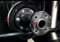
Hub extension.jpg

Rick...
 
I believe the drill hole in the extension was a witness mark for preserving the balanced position of the stock fan (would have been drilled through the fan, hub and weights once the parts were balanced as a set) - irrelevant since you are replacing with a Macy fan.

I do not believe that hole's position had anything to do with the position of the TDC mark hole in the pulley - you were able to line them up solely due to random chance.
 
Geo is correct. The small hole was drilled during the factory assembly to aid in positioning the balance plate the same during later service. If you have a non-original fan, then ignore the small hole...it won't align with the keyway, fan, plate, or anything else.

When installing the large extension bolt, the manual talks about using shims. These would be used as necessary, so that when the bolt is torqued, the angle of the crank handle would be correct for hand cranking. If you are not planning to hand crank, then you can ignore the shims.

The next thing is the lock plate for the bolt. You position this plate in a way that the fan bolts will go through it and lock the plate to hold the bolt. You may have to lift and reset it 1/6th of a turn to get the slots for the fan bolts to align.

Those are all the alignment items that I can recall...?
 
When installing the large extension bolt, the manual talks about using shims. These would be used as necessary, so that when the bolt is torqued, the angle of the crank handle would be correct for hand cranking. If you are not planning to hand crank, then you can ignore the shims.

The note about the origin of the drill hole from you and Geo makes sense. I had hoped to keep the crank function, but when I went to the aluminum radiator I had to scrap that idea. So the shims apparently aren't an issue.

However, you mentioned the 'torque' on that bolt. I couldn't find any note on a torque spec for that bolt in the list in the manual. Is there one that you guys are aware of?

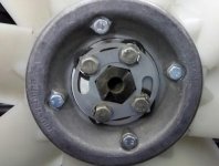
The Macy's fan does have a sturdy locking plate for that bolt. It just seemed to fit the bolt just right when I first assembled it. I suppose I'll just have to tweak the bolt so that the four bolts, the locking plate and the bolt head are aligned properly so the bolt can't back out.

This is before disassembly...

Macys fan hub.jpg

Rick...
 
I don't think I have ever seen that torque specified in the manuals. Tight enough. Not too tight (that can be expensive). I would guess about 50 ft lbs and some blue Loctite if you are wary.

...I suppose I'll just have to tweak the bolt so that the four bolts, the locking plate and the bolt head are aligned properly so the bolt can't back out...

Looks like the holes for the fan bolts are slotted so the plate can always be positioned after the crank bolt is done up.
 
Looks like the holes for the fan bolts are slotted so the plate can always be positioned after the crank bolt is done up.

I made that assumption at first myself. However, I seem to recall that the round lock plate should be rotated all the way counter clockwise up against the 4 bolts. It may have been in an exchange with Mark Macy, but I wouldn't swear to it. I've had discussions with a variety of folks on this. In any case, it would make sense to have it aligned like that so that the crank bolt could not back out any further even if there was some slippage of the slotted lock plate.
 
I do recall that if one is setting the dog bolt up for use of a hand crank, although shims are used, the torque is somewhat dictated by the need to end up with a 10:00/4:00 orientation. As I recall, I used shims to get in the ball park then settled for a decent torque that put the bolt where I wanted it. Perhaps this is why no torque number is provided.
 
I use 100ftlbs/lbs on the big bolt. The plate is placed over the bolt head in a way that the slots allow the 4 bolts to be installed. It may be full CCW...It may be full CW...or more likely somewhere in the middle. The 4 bolts then lock the big bolt in place.
 
Back
Top