• Hi Guest!
    You can help ensure that British Car Forum (BCF) continues to provide a great place to engage in the British car hobby! If you find BCF a beneficial community, please consider supporting our efforts with a subscription.

    There are some perks with a member upgrade!
    **Upgrade Now**
    (PS: Subscribers don't see this gawd-aweful banner
Tips
Tips

New tach, need matching speedo...

drooartz

Moderator
Staff member
Gold
Country flag
Offline
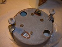
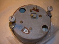
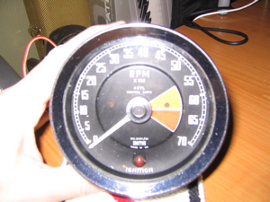
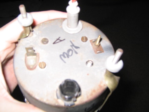
Got my new electric tach in today. It's RVI 2401/01, from a 66 or so Spridget (or similar). I think it's one of the last positive ground tachs. It's in good shape, and was sold as functioning. I don't have a running car right now to test it, but it looks good to me. Case isn't even all that rusty.

tachface.jpg
tachback.jpg


Two questions:

1. How do I wire this up?

2. Does anyone have the matching speedo to go with this that they'd be willing to sell? (I did check our new swap meet, but none there /bcforum/images/%%GRAEMLIN_URL%%/grin.gif) I'd need SN6142/00, which should be for the 4.22 rear end I have (at least my book says so). I'd like the speedo to match, and my Bugeye original needs to be restored still -- a project for later.
 
Sorry Drew--can't help. Have you checked ebay? I see similar tachs on there all the time. Usually listed above or beneath are the paired speedos.
 
I Just bought a (described as) good condition, working Bugeye speedo, so I'm just going to use that for now. I'll still keep my eyes open for that later model. Can't have too many parts around, now can you. /bcforum/images/%%GRAEMLIN_URL%%/grin.gif

Wish I could test it and try to figure out the wiring, but Tunebug is non-functional right now.
 
Drew

The later electric tach's have an inductive loop that senses ignition pulses. The pulse is amplified by a transistor inside the tach which drives the needle. It is attached by runing your White (I Think) ignition wire through the tach. (in one side out the other) There is a variable resistor on the board that can be accessed through a hole on the back of the tach that is used to calibrate it. There is also a capacitor on the circuit board that dries out with age, a replacement can be had at Radio Shack.
 
Hopefully someone will correct this if it is wrong but--
Drew
Wiring the tach is pretty simple, the wire in question replaces the one running from the coil to the distributer but it is very long and runs from the coil to the tach, wraps around the tach sensor (stuff on the right on your picture) 3 times and then returns to the distributer. For test just run the wire but then making it look like it is in the wiring harness will be the interesting part. A wire from the ignition switch (or hot wire frrom the fuel gauge) to the power plug on the tach and a GOOD ground should complete the operation.
By the way- you need to get a tach sensor assy to plug into the tach where the threaded post is (yours is missing)
Bill
 
So do I need a "tach sensor assembly?" Anyone got a picture so I know what I'm looking for.
 
Thanks for the eBay link.

Since my first post in this thread, I've actually decided to go in a different direction. I found a functioning Bugeye speedo on eBay, and was able to win it for a reasonable sum. I'm now going to try to delve into the mysteries of electronic tach repair and swapping, and see if I can update an original Bugeye-look tach with reliable electronic bits. I've got a bit in on a restorable Bugeye tach, and hope to be able to use that face, and the 2 electronic tachs that I have, to make one good tach.
 
Is a guide someplace on how to just mount electronic tac guts behind a BE face.
 
That's probably Doug's reference you're talking about:

https://www.britishcarforum.com/lore/article.php?id=063

I've been reading this and trying to gain a better understanding so I can tackle it in the future. Right now i can read the words, but true understanding escapes me a bit. /bcforum/images/%%GRAEMLIN_URL%%/grin.gif
 
A picture of the adaptor would be handy. If I can get the RVI tach I have to function, then I'll at least have a temporary solution to get me by for a while.
 
Here is a tach with some of the stuff, it is missing the nylon wire holder which I can't find right now.
Bill
-----------
OK!!!!
 

Attachments

  • 4563-DSCN0219.JPG
    4563-DSCN0219.JPG
    113.4 KB · Views: 166
  • 4564-DSCN0220.JPG
    4564-DSCN0220.JPG
    114.3 KB · Views: 169
To post a picture, use the "Reply" button, not the "Quick Reply." Once there, you will see a link for the "File Manager" which will allow you to add the picture.
 
OK-- I screwed-up--
The tach is not wired as I said (wire from coil to distributer goes to tach and back). The wire should go straight from the coil to the distributer). The FEED wire from the ignition switch makes a detour to the tach and then to the coil (hot side obviously) and the short wire goes from the other side of the coil to the distributer.
Bill
 
I'll have to hunt down one of those little nylon jobbies one of these days.
 
Drew, when you're ready to start the tach swap process feel free to email me. I'll be happy to help as best I can.

Billm, you were not wrong regarding the wiring. The RVI tachs go in series with the power flowing through the coil. There are two ways to do that. On cars where the RVI tachs were installed by the factory this was often as you described: Ignition switch, loop on back of gauge, out to the high-side of the coil. Where the RVI tachs were added later, it is easier to run a pair of wires through the firewall. One wire would go to the low side of the coil, back to the tach (formed into a loop on the back of the gauge), then back to the terminal on the side of the distributor. Effectively, that wiring scheme replaces the black/white wire that's normally between the coil and dizzy.

It's been posted before but it's worth repeating that RVI tachs are frequently unhappy when you've installed electronic ignitions. Assuming you've still got points and the caps haven't dried out, I'm sure it will work for you. I'm not sure about "three loops" on the back of the gauge as was mentioned earlier. I've only seen single loops on factory installed tachs but I have heard of some people getting better tach performance with two loops. Also, if the tach acts a little odd (but works), reverse the direction of the looped wire on the back of the tach.

Use the search feature of this board to look for other tach threads. I remember that within the past three months someone posted a thread about DIY bench calibration of RVI tachs using a signal you can create (safely) from the 60 Hz current in normal household outlets (perhaps using a little wall-wart transformer.
 
Back
Top