I don't know that 45 amps would burn up the original ammeter; but the first time I did this conversion, it did appear that the 60 amps at every startup was damaging the movement. The needle would whack the peg pretty hard and after a few cycles of that, started to stick. At any rate, I don't like seeing instruments hit the peg like that and it was an easy thing to fix. Probably take longer to explain than to do it

To understand the shunt, you need two things: All electrical conductors (except superconductors) have some resistance; and two resistances in parallel will divide the current in inverse proportion to their resistance. If they are equal, then each gets half the current.
Internally, the ammeter is just a loop of wire (the magnetic field from the wire is what moves the needle). So, if you add another wire in parallel with the same resistance as the ammeter, it will take half of the current. With only half of the current going through the meter, it indicates half of the actual current.
For my first go-round, I just added strands of steel "handy wire" (aka baling wire) across the ammeter until I liked the result. Steel has a higher resistance than copper, so I was effectively paralleling multiple strands to get a low enough resistance.
To get the right effect, I first noted the ammeter deflection with the headlights on (engine off), and then kept adding strands until I got half as much deflection. Probably not "best practice", but I just left the ammeter hanging on the wires while I went through the process of adding strands and checking the reading, so it went really quick. Not very precise of course, but precision really isn't much of an issue here. Really, all you want to know is whether the battery is being charged or discharged, and whether it is a little or a lot. It just doesn't matter if full scale is 60 amps or 70 amps (as long as it will take the full current).
If memory serves, I wound up with 4 strands of what was probably 18 AWG steel wire, but of course YMMV. Sorry I don't have a photo, but I didn't own a camera then (and wouldn't have thought to take one even if I did have a camera).
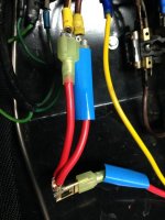
Years later, when I got the powder coated center panel seen above, I spent some time measuring the actual resistance of the ammeter. The two original TR3 ammeters that I checked were both very close to 1.2 milliohms (.0012 ohms), although a friend checked his early TR6 ammeter and found over twice that (2.7 milliohms). Consulting a copper wire chart like this one
https://www.powerstream.com/Wire_Size.htm, I found that 3-1/2" of 16 AWG wire would be about the same resistance. So, that's what you see in the photo above.

 Hey Guest!


 but were afraid to ask:
  STOP!! Never post your email address in open forums. Bots can "harvest" your email! If you must share your email use a Private Message or use the
  smilie in place of the real @
 Pretty Please - add it to our Events forum(s) and add to the calendar! >>