• Hi Guest!
    You can help ensure that British Car Forum (BCF) continues to provide a great place to engage in the British car hobby! If you find BCF a beneficial community, please consider supporting our efforts with a subscription.

    There are some perks with a member upgrade!
    **Upgrade Now**
    (PS: Subscribers don't see this gawd-aweful banner
Tips
Tips

Hot cams and advanced ignition

Question for when you return (Hope you have a great vacation, BTW), what kind of plug wires do you have?

Reason I ask is that I have the bumblebee wires on mine, which are non-resistor wires. They caused interference with my strobe light. I had to replace the #1 wire with an old resistance wire to make it work properly.

John, still at home and short prior take off! I took all my sparkplug wires out and found, that they are of the old standard type with no resistance. But I have 90° NKG LBO5F sparkplug connectors with 5 k-Ohm resistance. Would you recommend to replace the old wires with bumblebee wires an keep the connectors or what kind of connectors do you have? By the way my connectors don't have rubber caps anymore; would that be a problem, too?
 
Lutz, I may be repeating what has been said, but I have been thinking about what should be obvious mechanical alignment. You have said that you checked the mark on your pulley with top dead center of #1 piston. But I'm not sure that you indicated that you were sure you had the piston at top dead center of the compression stroke. I think maybe with the cylinder on the exhaust stroke the engine could be timed to run with the distributor turned really far. I may be all wrong on this. But the point I want to make is that mechanically and visually if the timing mark on the pulley is set to the right of the pointer about 1/2 inch to 3/4 of an inch and the points are turned to open just then, then the timing will be within 10 to 15 degrees give or take a smidgen of where it belongs. It could not be at 45 degrees.
 
Bob, before I go on vacation I want to let you know what I found when I performed the test you suggested. I hooked up my strobe to every sparkplug wire to find out which one is firing close to 15° BTDC. I still can't believe what I found. People must believe I'm crazy!

The strobe flashes for all 6 wires at 45° BTDC of #1 piston??? So, usually I'd assume the strobe is trash. Not in this case, because the other day I tried a strobe of a different manufacturer with the same result and I did a static timing with the same result, at least for piston #1. What is this now???

Best thing to do is to go on vacation and then let BOSCH take care of it!?

I'm going back to one of my first posts in the original thread: If you get the same reading by hooking up the light to all of the wires, then it sounds to me like bad RF interference, most likely from somewhere in the ignition system, messing with the timing light or its inductive pick-up. I think the idea of taking the car to the Bosch Station is an excellent idea at this point. Jim
 
John, still at home and short prior take off! I took all my sparkplug wires out and found, that they are of the old standard type with no resistance. But I have 90° NKG LBO5F sparkplug connectors with 5 k-Ohm resistance. Would you recommend to replace the old wires with bumblebee wires an keep the connectors or what kind of connectors do you have? By the way my connectors don't have rubber caps anymore; would that be a problem, too?
Lutz, To me, the old standard wires have resistance in the wire; they use a carbon fiber wrapped around a fiber core. If yours have no resistance, they will likely cause the interference as mentioned by Jim. Like I wrote (or tried to write), the bumblebee wires have no resistance, my connectors have no resistance but my plugs do. The lack of resistance in my wires interfered with my strobe light. I had to substitute a resistance wire for #1 plug to get the strobe to read correctly.
 
Lutz, I may be repeating what has been said, but I have been thinking about what should be obvious mechanical alignment. You have said that you checked the mark on your pulley with top dead center of #1 piston. But I'm not sure that you indicated that you were sure you had the piston at top dead center of the compression stroke. I think maybe with the cylinder on the exhaust stroke the engine could be timed to run with the distributor turned really far. I may be all wrong on this. But the point I want to make is that mechanically and visually if the timing mark on the pulley is set to the right of the pointer about 1/2 inch to 3/4 of an inch and the points are turned to open just then, then the timing will be within 10 to 15 degrees give or take a smidgen of where it belongs. It could not be at 45 degrees.


First of all let me say that I made sure that when #1 piston was at TDC it also was at the end of compression stroke. Both valves were closed and the valves of zylinder #6 were overlapping.

My timing marks are set in accordance with the following table and foto:

Timing marks.jpg

The yellow measuring tape shows cm where 1 cm = 10 mm

Timing

circumference pulley
mminch
° BTDC
59623.5
120.1
580.3
10170.7
15251.0
20331.3
25411.6
30502.0
35582.3
38632.5

So with my pulley which has a circumference of 23.5" the 15° position (red mark) is about 1" to the right of TDC, but like I said this is not the time #1 zylinder is fired. In my case it takes place at 45°.
 
Lutz, To me, the old standard wires have resistance in the wire; they use a carbon fiber wrapped around a fiber core. If yours have no resistance, they will likely cause the interference as mentioned by Jim. Like I wrote (or tried to write), the bumblebee wires have no resistance, my connectors have no resistance but my plugs do. The lack of resistance in my wires interfered with my strobe light. I had to substitute a resistance wire for #1 plug to get the strobe to read correctly.

Thank you for your reply. I just bought new plugwires, unfortunately no bumblebee wires, which you certainly not get araound the corner when you are in a hurry. I just wanted to try some other wires befor my vacation starts. Well, at least it was a little success and confirmed your and John's suspicion. The strobe shows now 30° BTDC. I think you both are leading me to the real cause. It must have something to do with the plugwires. The new wires again have no resistance, so as soon as I'm back I'll try to find some with resistance and see what is happening! May be BOSCH has those kind of wires and can do the job!
 
Lutz,
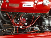
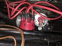
Perhaps you can upload a picture of the distributor cap and wires in position on the engine. So we can see the angle of the distributor and which wire goes to which cylinder.

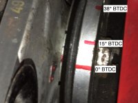
Back from my vacation and here are the pictures.

Verteiler geschlossen.jpgVerteiler offen.jpgZĂĽndungsmarkierungen groĂź.jpg

The pictures have been taken at the same time when #1 zyl. was at TDC (the long red line on the pulley was at 0° BTDC)
 
Last edited:
Lutz, To me, the old standard wires have resistance in the wire; they use a carbon fiber wrapped around a fiber core. If yours have no resistance, they will likely cause the interference as mentioned by Jim. Like I wrote (or tried to write), the bumblebee wires have no resistance, my connectors have no resistance but my plugs do. The lack of resistance in my wires interfered with my strobe light. I had to substitute a resistance wire for #1 plug to get the strobe to read correctly.

John, after having returned from vacation I substituted the wire for #1 plug with a resistance wire but the strobe light is reacting like before. No changes whatsoever!
 
Lutz, it could be another wire, several wires, or something else in the ignition/electrical system causing noise in the timing light or the pick-up. The Bosch station can probably help you get this sorted out, and that would be my next stop, because at this point, I'm clueless. It sounds like you have thoroughly checked almost everything else, and since substituting the old points distributor showed no difference, that probably eliminated the Pertronix and the newer distributor as the cause of the noise.

Sorry to have helped take you down the camshaft rabbit hole, but at that point, I thought the noise/interference idea had been eliminated. However, at least you now know that the cam is probably timed correctly, that it may be a performance grind, and that most everything appears to be set up correctly. The hotter cam may require a few degrees of ignition advance, but certainly not what you are seeing. Now, I would almost bet that it is electrical noise messing with your timing measurement, but the timing is probably fairly close to where it should be - if the car is running well, and there is no pinging under load. Jim
 
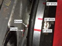
Lutz, I apologize if I am leading you down empty holes, because i am not an expert, just a guy who usually just follows the book for the last 40 years doing my wrenching. But in your latest pics i see two things that give me question. One is that when you show your crank dampener and the mark at top dead center, is there a small groove cut into your dampener at that point where your painted over with red. Every Healey dampener that I have seen has a groove cut into the dampener at TDC. There are no other degree marks but there is a groove at TDC. I can't tell in your pic if it is there. 2nd, when I look at the pic that shows the distributor rotor, the rotor is pointing down at the number 1 plug wire. I'm pretty sure that the Healey distributors are installed with the #1 wire at about the 1:00 oclock position. Obviously you can position the distributor in relatively any position as long as the rotor fires #1 when the #1 cylinder is ready for it, but these are 2 anomalise that I see.
 
Vette's observations are correct. I would also expect some kind of permanent "V" slot or hole at TDC. I missed that in your pictures, and also the rotor at 7:00 for #1 - I just verified that it did seem to line up with the correct wire. This is tough to do from 6000 miles away!
 
Pictures from an original manual show how all the elements need to be positioned:
PointerNotchTDC.JPG
LowerDriveItem112.JPG
LowerDrivemosss.JPG
UpperDriveItem114.JPG
UpperDriveMoss.JPG

TDC notch is distinct and square. Lower drive Moss #112 in "twenty-to-two" position. Upper drive #114 same with smaller arc at bottom.
The drive dog #116 should be pinned to the shaft of the Mallory such that the distributor rotor points in the general direction of the #1 spark plug.

Note #114 and #113 are pinned together at the factory and should be parallel to each other.

Logically, it would seem the problems we're discussing have to do with the strange position of the rotor. I would want to verify the upper and lower drives are in the factory position per the manual when the #1 piston is at TDC per the crank pulley mark.

The fact that the Mallory requires one to drill the shaft to fit the standard drive dog would seem to be a good opportunity to mess things up.
 
Lutz, I apologize if I am leading you down empty holes, because i am not an expert, just a guy who usually just follows the book for the last 40 years doing my wrenching. But in your latest pics i see two things that give me question. One is that when you show your crank dampener and the mark at top dead center, is there a small groove cut into your dampener at that point where your painted over with red. Every Healey dampener that I have seen has a groove cut into the dampener at TDC. There are no other degree marks but there is a groove at TDC. I can't tell in your pic if it is there. 2nd, when I look at the pic that shows the distributor rotor, the rotor is pointing down at the number 1 plug wire. I'm pretty sure that the Healey distributors are installed with the #1 wire at about the 1:00 oclock position. Obviously you can position the distributor in relatively any position as long as the rotor fires #1 when the #1 cylinder is ready for it, but these are 2 anomalise that I see.

You don't have to appoligize at all! I am happy for every suggestion.
First of all there is not a groove on the dampener but on the pulley as you can see from the following picture.

ZĂĽndungsmarkierungen groĂź.jpg

My red mark at 0° BTDC is about 1-2° off which shouldn't be a problem.

The distributor is not the origanal one, it's a Mallory twin contact dizzy. But as you said, you can have the dizzy positioned in any position as long as the rotor points to #1 plugwire when the crank is at TDC. I think the position of the dizzy is mentioned in the workshop manual just for the reason that the original dizzy has an vacuum advance system mounted to the dizzy, so it's not possible to adjust the timing by turning the dizzy 360°. The vacuum advance would hit the engine.
 
Last edited:
Pictures from an original manual show how all the elements need to be positioned:
View attachment 45424View attachment 45423View attachment 45425View attachment 45426View attachment 45427
TDC notch is distinct and square. Lower drive Moss #112 in "twenty-to-two" position. Upper drive #114 same with smaller arc at bottom.
The drive dog #116 should be pinned to the shaft of the Mallory such that the distributor rotor points in the general direction of the #1 spark plug.

Note #114 and #113 are pinned together at the factory and should be parallel to each other.

Logically, it would seem the problems we're discussing have to do with the strange position of the rotor. I would want to verify the upper and lower drives are in the factory position per the manual when the #1 piston is at TDC per the crank pulley mark.

The fact that the Mallory requires one to drill the shaft to fit the standard drive dog would seem to be a good opportunity to mess things up.


First of all let me thank you for the pictures you have attached to your posting.
But like I already have mentioned above, the distributor is not the origanal one, it's a Mallory twin contact dizzy. In my oppinion this dizzy can be mounted to any position as long as the rotor points to #1 plugwire when the crank is at TDC and of course all other plugwires are connected to the rotor cap in firing order. I think the position of the dizzy is mentioned in the workshop manual just for the reason that the original dizzy has an vacuum advance system mounted to the dizzy, so it's not possible to adjust the timing by turning the dizzy 360°. The vacuum advance would hit the engine.
 
The Mallory has an adjustable mechanical advance, You can limit how much You get overall. Maybe that is out of whack.
 
Lutz,
What I'm suggesting is to mark the clamp to the base (picture 5) such that you can undo the two bolts and remove the distributor without disturbing the timing. You should see the drive dog as shown in the picture. If it's in another position the teeth on #112 are misaligned to the engine. You should be able to pull #112 out of the engine with a bolt (see 3 & 4 below from the Haynes 100/6-3000 manual pg 52) and realign the dog per picture 5. Then your mallory should be in the ballpark so you can time the engine correctly. Otherwise the timing is occurring at the wrong place on the crank shaft.

Respectfully, I don't think you can troubleshoot this situation until you determine the drive dog is in the correct position. Then you have a baseline and can time your Mallory with the crankshaft marks.
HaynesDriveGear.jpg
 
Originally posted by Lutz
The distributor is not the origanal one, it's a Mallory twin contact dizzy. But as you said, you can have the dizzy positioned in any position as long as the rotor points to #1 plugwire when the crank is at TDC. I think the position of the dizzy is mentioned in the workshop manual just for the reason that the original dizzy has an vacuum advance system mounted to the dizzy, so it's not possible to adjust the timing by turning the dizzy 360°. The vacuum advance would hit the engine.

You are correct, without the vacuum advance to worry about, the orientation of the distributor is not important as long as the rotor points at whichever one you use as number 1 and that corresponds to TDC (and the rest of the firing order correct). I believe the offset dog in the distributor drive is just so you can remove the distributor to install points or other service and reinstall without worrying about getting it 180 out. With the stock vacuum advance distributor it is a little more hassle, but I also run a Mallory and I always remove it and 'bench' install points & re-install (it's a lot easier of you drop a small screw when it's on the bench).
 
Look people, this has NOTHING to do with the assembly of engine, distributor, coil, camshaft or the number of angels dancing on the head of a pin.
Quite simply, Lutz's car runs fine, it's just that he measures the idle advance as 45deg. Quite clearly, that's not so, therefore the method of measurement is incorrect.

I suspect interference with the strobe, possibly from the plug wires.

Lutz, when you had the points back in, did you measure static advance the old-fashioned way, with a 12v bulb and not a strobe? Interference would then play no part.
 
Back
Top