

-
 Hey Guest!
British Car Forum has been supporting enthusiasts for over 25 years by providing a great place to share our love for British cars. You can support our efforts by upgrading your membership for less than the dues of most car clubs. There are some perks with a member upgrade!**Upgrade Now**
(PS: Upgraded members don't see this banner, nor will you see the Google ads that appear on the site.)
You are using an out of date browser. It may not display this or other websites correctly.
You should upgrade or use an alternative browser.
You should upgrade or use an alternative browser.
TR2/3/3A Generator Output
- Thread starter TR3MT
- Start date

auprichard
Senior Member
Offline
I have an alternator in all 5 of my cars. Your specific questions:
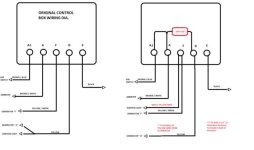
- Bypassing the regulator involves joining the large yellow, brown/white and brown/blue and then joining the smaller yellow with the yellow/green (see diagram). I pull the guts from the regulator and join the appropriate terminals as described in a recent Rusty Beauties youtube by Elin Yakov.
- The ammeter will still work, but a voltage gauge is a good idea. Remember it is fed by a simple ignition (white wire) feed. Make sure you tie off and insulate the ammeter wires as they are live all the time.
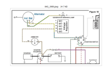
- The red ignition light will work - see attached diagram for a single pole alternator. Some alternators however have two poles in addition to the main stud: these will require an ignition feed, either from the on/off switch or a wire from the coil or fuse box.
- Bypassing the regulator involves joining the large yellow, brown/white and brown/blue and then joining the smaller yellow with the yellow/green (see diagram). I pull the guts from the regulator and join the appropriate terminals as described in a recent Rusty Beauties youtube by Elin Yakov.
- The ammeter will still work, but a voltage gauge is a good idea. Remember it is fed by a simple ignition (white wire) feed. Make sure you tie off and insulate the ammeter wires as they are live all the time.
- The red ignition light will work - see attached diagram for a single pole alternator. Some alternators however have two poles in addition to the main stud: these will require an ignition feed, either from the on/off switch or a wire from the coil or fuse box.
Attachments


Offline
Somewhere I’m sure I read that the output of the alternator will burn up the ammeter or wires to it, and that it must be bypassed. I’m seeing different positions now on that issue. Can you clear up that confusion?
Also, I’m not sure what is being shown in the far right upper side of the second diagram posted by Auprichard under where it says Figure 10. What is that?
Also, I’m not sure what is being shown in the far right upper side of the second diagram posted by Auprichard under where it says Figure 10. What is that?

CJD
Yoda
Offline
Yep, good point! If you are installing an alternator that is capable of more than 30 amps, it could permanently damage the OEM ammeter. In the archives you find the fix provided by our late Randall. He explains how to install a resistor to the ammeter so it will take 60 amps...of course the mod means the actual amps will be twice the gage reading, after the mod.
Offline
So if I’m understanding the diagrams above, with an alternator conversion, the battery terminal of the alternator is routed to one terminal of the ammeter and the voltage regulator/control box is completely bypassed, but it is probably necessary to put a resistor in the line between the alternator and the ammeter. Or, I could eliminate the ammeter and replace it with a close replica voltage gauge.
The new wiring to the dash indicator light seems a simple step, wired as shown in the diagram.
Presumably, it will be clear what happens to all the wires pulled off the control box which becomes obsolete.
I’m thinking I’ll give it all a try.
The new wiring to the dash indicator light seems a simple step, wired as shown in the diagram.
Presumably, it will be clear what happens to all the wires pulled off the control box which becomes obsolete.
I’m thinking I’ll give it all a try.

Gerald_Gordon
Senior Member
Offline
Regarding the resistor used to double the range of the 30-0-30-ampere ammeter to be 60-0-60 amperes, it it wired in shunt (parallel) across the meter's terminals, not in series between the alternator and the meter. Alternatively, the coil inside the meter could be rewired and a new 60-0-60 face could be made, as West Valley Instrument Specialists did with mine several years ago. As for Randall Young's external shunt, I believe that it was 3.5 inches of 16 AWG copper wire.


Offline
A Powerlite alternator looks exactly like our generators, and even are available in positive earth. Lucas even makes them now.Thanks. Looks like I will be installing an alternator.

Offline
Not much to worry about, for two reasons:Somewhere I’m sure I read that the output of the alternator will burn up the ammeter or wires to it, and that it must be bypassed. I’m seeing different positions now on that issue. Can you clear up that confusion?
1. These ammeters consist internally of a loop of very heavy wire. It can handle 60 amps easily. Some of the connections might be more of a problem, but I suspect they would be OK.
2. With an alternator, you will rarely see the ammeter move more than a few amps from zero. Remember, the ammeter doesn't read the load current; it reads the battery's charge/discharge current, and modern alternators balance that very well.
Thank you Steve for your insight. I have been running a single wire alternator from British Wiring on my TR3 since 2017. My ammeter does not have a “Charley” shunt and I have no issues. The ammeter performs just as you have described it.
Frank D……..
Frank D……..
Gerald_Gordon
Senior Member
Offline
Steve, you write that the ammeter rarely moves more than a few amperes from zero, which has been my experience, too. However, the occasion on which mine failed was when, having drained the battery by having left the headlights on overnight, I started the car by rolling it downhill and popping the clutch, causing the battery to draw the full 67-ampere output of the Ford alternator, which immediately fused the 30-0-30-ampere meter.
Offline
Well, I'd be interested in examining an ammeter that failed that way. I'd love to do a post-mortem on it. If the internal loop is no. 14, for example, it should carry 60+ amps without fusing. The connections could be a different story, though; that's where most of the resistance is, so I'd be less surprised if the connections are what burned out. Conversely, a shunt, may extend the range of the meter but it will do very little to prevent the connections from melting.
Also, if it's not like the Smiths and Jaeger meters I'm familiar with, it could be entirely different as well.
Another thing to remember: automotive generators and alternators implement a float charger: they are designed for use with a battery that is at least partially charged. If the battery is totally flat, it's a good idea to charge it awhile on an external charger, just to get it up to 12V or so, then the car's charging system can safely take over. The generators in early Porsches, for example, are notorious for melting their internal soldered connections if you try to run one with a totally flat battery.
Also, if it's not like the Smiths and Jaeger meters I'm familiar with, it could be entirely different as well.
Another thing to remember: automotive generators and alternators implement a float charger: they are designed for use with a battery that is at least partially charged. If the battery is totally flat, it's a good idea to charge it awhile on an external charger, just to get it up to 12V or so, then the car's charging system can safely take over. The generators in early Porsches, for example, are notorious for melting their internal soldered connections if you try to run one with a totally flat battery.
CJD
Yoda
Offline
Gerald is not the first. If you search the archives, this is common with an alternator conversion. Steve, you are right that if you keep your battery charged, the load from the alternator through the ammeter will always be well below 30 amps. It's the time you start the car with a dead battery that the alternator will peg the ammeter and ruin it. Most of the posts say the ammeter pegs above 30 amps, and never moves again.
It is a simple mod to add the shunt.
It is a simple mod to add the shunt.
Gerald_Gordon
Senior Member
Offline
Steve, I would send you my fused ammeter for examination except that West Valley Instrument Specialists has already modified it to double its range. (They also built a Jaeger clock to resemble the other secondary instruments, complete with a domed lens, and it is installed in the hole for the ammeter, which remains uninstalled. Until I can figure out how to mount all five secondary instruments, the red no-
 charge indicator will have to suffice.)
Offline
Well, OK. I'm not going to discount anyone's experience, but I'm still skeptical. I can't see how something that handles 30A easily will undergo a catastrophic failure at 60. The wire loop, probably #14 or larger, has a fusing current between 150A and 200A, so there is no way that 60A will melt it. It might melt the solder in the connections, but that won't be sudden, if it happens at all. Remember, the pointer is coupled to that loop only by a weak magnetic field, and it carries no current. Doubling it is unlikely to cause mechanical damage.
I suspect people who report ammeter damage have underestimated the short-circuit output current of the alternator, which could be a lot higher than the rated output. Or simply made a mistake in connecting it. Either of which is likely to cause damage, with or without a shunt.
As for shunts...you're dealing with hundredths or thousandths of an ohm resistance, most of which is in the connections, not the wire. A minuscule change in the connections (like adding an extra washer) can make a proportionately huge change in the resistance, which will strongly affect the full-scale reading. You can't be sure the shunted meter is correct unless you check the calibration with the shunt in place. That's one reason why I've never used one, as I don't have the equipment to calibrate it.
I suspect people who report ammeter damage have underestimated the short-circuit output current of the alternator, which could be a lot higher than the rated output. Or simply made a mistake in connecting it. Either of which is likely to cause damage, with or without a shunt.
As for shunts...you're dealing with hundredths or thousandths of an ohm resistance, most of which is in the connections, not the wire. A minuscule change in the connections (like adding an extra washer) can make a proportionately huge change in the resistance, which will strongly affect the full-scale reading. You can't be sure the shunted meter is correct unless you check the calibration with the shunt in place. That's one reason why I've never used one, as I don't have the equipment to calibrate it.
Offline
I’m paraphrasing, and maybe not fully appreciating the details of the debate, but the Moss alternator conversion instructions appear to state that while a generator system rarely generates more than 18–22 amps, fitting a high-output (60+ amp) alternator through the stock dash ammeter risks overheating the gauge terminals, melting adjacent insulation, and ruining internal instrument components due to total charging current passing directly through the gauge.
I have alternator and did not want to modify ammeter without upgrading all the associated wiring ,which is mostly under the dash,for described worst case.
Since I was rewiring everything I eliminated the ammeter,replaced by similar looking voltmeter and now no high current wires or gauges under the dash.
I think an ammeter is more suited for a generator and a voltmeter is more suited for an alternator.
Anyway the wiring sure is easier.
Tom
Since I was rewiring everything I eliminated the ammeter,replaced by similar looking voltmeter and now no high current wires or gauges under the dash.
I think an ammeter is more suited for a generator and a voltmeter is more suited for an alternator.
Anyway the wiring sure is easier.
Tom
I installed a 40a Kubota type ebay$75 alternator 12 years and 25k miles ago no problems.
I have an electric fan with a wizard radiator ,moss fan eliminator thin belt kit and the fan load doesn't even factor in as it is almost never on.
This was very easy install as the alternator came with thin belt pulley that matched moss crank pulley.A little bending of the original bracket and some spacers,no kit needed.
The alternator came with wire for warning light.
The voltmeter connects to an ignition on wire and a ground.Use the key switch terminal or the start button,which only has one wire on the terminal..
The ammeter ,regulator, and two fuse holder were all removed and a voltmeter and 4 fuse original lucas cobra and jag type fuse holder installed where the regulator was.
Tom
I have an electric fan with a wizard radiator ,moss fan eliminator thin belt kit and the fan load doesn't even factor in as it is almost never on.
This was very easy install as the alternator came with thin belt pulley that matched moss crank pulley.A little bending of the original bracket and some spacers,no kit needed.
The alternator came with wire for warning light.
The voltmeter connects to an ignition on wire and a ground.Use the key switch terminal or the start button,which only has one wire on the terminal..
The ammeter ,regulator, and two fuse holder were all removed and a voltmeter and 4 fuse original lucas cobra and jag type fuse holder installed where the regulator was.
Tom
Last edited:

Offline
You expected a generator to make good power??? You are lucky if it will even charge
the battery! When stressed with accessories, the old lump will often get hot and smoke out,
if the battery is low too. Always run the best battery you can get. It will stress the system
less and add life to the generator.
In the end, if you need more amps than it can make, get an alternator.
The old Lucas was never able to do too much more than the bare minimum.
Mad dog
the battery! When stressed with accessories, the old lump will often get hot and smoke out,
if the battery is low too. Always run the best battery you can get. It will stress the system
less and add life to the generator.
In the end, if you need more amps than it can make, get an alternator.
The old Lucas was never able to do too much more than the bare minimum.
Mad dog