Hey Guest!

 Hey - did you know if you click on the title of a thread it will take you to the first unread post since you last visited that thread?
 but were afraid to ask:
  STOP!! Never post your email address in open forums. Bots can "harvest" your email! If you must share your email use a Private Message or use the
  smilie in place of the real @
 Pretty Please - add it to our Events forum(s) and add to the calendar! >>
PeterK
Yoda
Offline
Before reading Paul's excellent fuel pump rebuild instruction, I tanked and disassembled my fuel pump. I noticed a ruber seal around the diaphram shaft and used a pick to tear it out through the hole in the cup that holds it in. Then I lightly pried around the inside of the cup hole to remove it. No go, the cup wasn't coming out without risk of ruin. THEN, I read Brosky's write-up that said"
"It's also too bad that the cups are not there because you have two new seals for the diaphragm shaft, but no way to get the very thin wall cup out without ruining it."
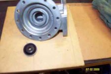
Well, merde! Why would TRF sell you a seal that cannot be installed? Answer is, they didn't. Here's how I removed mine and it was easy.
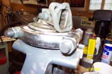
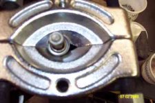
I inserted a 3/8" bolt through the hole in the thin wall cup and inserted a matching hex nut inside the pump body, threading them together. I inverted the pump body and clamped the head of the 3/8" hex bolt in my vise. Then I used a clamshell clamp used for pressing bearing off and lightly and evenly wedged it under the head of the hex bolt. These clamshell clamps are used when removing pressed-in bearings to add the pressure around the bearing holder instead of prying around each edge. It's like having a full circumference of screwdrivers all prying at the same time and at the same intensity. So after the clamshell was lightly set, I simply grabbed it from each side and pulled upwards. Voila. Done.
I'll go in and get a flash card so you can have a pic shortly.
"It's also too bad that the cups are not there because you have two new seals for the diaphragm shaft, but no way to get the very thin wall cup out without ruining it."
Well, merde! Why would TRF sell you a seal that cannot be installed? Answer is, they didn't. Here's how I removed mine and it was easy.
I inserted a 3/8" bolt through the hole in the thin wall cup and inserted a matching hex nut inside the pump body, threading them together. I inverted the pump body and clamped the head of the 3/8" hex bolt in my vise. Then I used a clamshell clamp used for pressing bearing off and lightly and evenly wedged it under the head of the hex bolt. These clamshell clamps are used when removing pressed-in bearings to add the pressure around the bearing holder instead of prying around each edge. It's like having a full circumference of screwdrivers all prying at the same time and at the same intensity. So after the clamshell was lightly set, I simply grabbed it from each side and pulled upwards. Voila. Done.
I'll go in and get a flash card so you can have a pic shortly.