• Hi Guest!
    You can help ensure that British Car Forum (BCF) continues to provide a great place to engage in the British car hobby! If you find BCF a beneficial community, please consider supporting our efforts with a subscription.

    There are some perks with a member upgrade!
    **Upgrade Now**
    (PS: Subscribers don't see this gawd-aweful banner
Tips
Tips

TR2/3/3A Ford Alternator Conversion Problems

mastaphixa

Jedi Trainee
Country flag
Offline
I have done a search on this and similar subjects without finding help for my situation.

The car: 1960 TR3 converted to Negative ground and Motorcraft Alternator with external voltage regulator.

The problem:
1. Generator light is on bright with the engine running.
2. Battery shows the same voltage engine on or off.

The conversion:
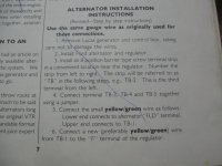
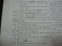
I found what looks like the conversion performed to this car with documentation included with it, namely a document titled "More BS about TR's" by Bob Schaller. I have attached an image of the cover, wiring diagram and instruction for conversion that a previous owner had accomplished with this post.

My questions:
1. There are only 2 wires attached to the alternator.
a. Large Yellow attached to the BAT terminal on the Alternator.
b. Small Yellow/Green attached to the FIELD terminal on the Alternator.

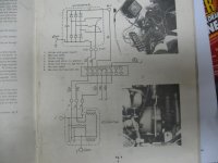
The wiring diagram shows a wire from the STAT terminal on the Alternator to TB2. It's not connected to anything. This wire does not exist. I suspect there is an error in the wiring diagram or the instructions?

The wiring diagram shows a ground wire run from the Alternator to ground. Would the physical mounting of the Alternator to the block suffice for this?

Observations:
1. Revving the engine has no effect on battery voltage.
2. The belt is loose compared to the modern cars (Miatas) that I am used to, but is appropriate for this car from what I have read.
3. Placing a DC Voltmeter between TB 3 and ground produce 12.9 VDC at idle.

Thanks for any advice in advance.
 

Attachments

  • IMG_2526.jpg
    IMG_2526.jpg
    50.3 KB · Views: 135
  • IMG_2527.jpg
    IMG_2527.jpg
    47.6 KB · Views: 128
  • IMG_2533.jpg
    IMG_2533.jpg
    54.2 KB · Views: 128
  • IMG_2534.jpg
    IMG_2534.jpg
    58.2 KB · Views: 130
Wow, talk about a blast from the past. I did that same conversion (on my own, not from Bob's instructions) some 30 years ago. But I followed the Ford factory wiring (even using a wiring harness from a car in the junkyard), while it appears that Bob has modified the circuit a bit.

Normally, the S terminal on the regulator would connect to the Stator terminal on the alternator. This provides a signal to the regulator when the alternator is turning, so it "knows" to apply field current to the alternator. From what I've read, this was done out of concern that the field (aka rotor) in the alternator might overheat if current was applied for a long time with the alternator not turning. But Bob's diagram shows the S terminal wired to the ignition switch instead, so the regulator is active whenever the key is on. That replaces the wire from the Stator terminal.

Peering into my crystal ball (which is actually an old headlight bulb), I'd guess that Bob originally wired ala Ford, and discovered the same thing I did : the alternator would often not start working until the engine was revved annoyingly high. His solution was to rewire the S terminal to the ignition switch and abandon the wire to the Stator terminal. Mine was to add a resistor across the warning light on the dash. Anyway, that is my best guess as to why he showed the unused wire. His wiring should work (except for the part about the rotor overheating).

In short, I think the diagram and instructions are the way Bob intended.

On to why it doesn't work: Have you tried checking the voltage on the Field terminal with the engine running? If the battery voltage is only 12.9, you should be seeing close to that much on the field terminal. If so, and it isn't putting out anything, the alternator is bad. If you aren't getting 12.9 then likely the regulator has failed. Most auto parts stores (eg O'Reillys) can test them for you, usually for free.

The ground wire is "belt and suspenders", not really needed. But Ford included it, so I did too.

As a side note, I recently completed another conversion using a "mini" 45 amp Japanese alternator, and I like the results much better. Fits the space better, uses the same belt and the belt is actually slightly easier to change than with the stock generator. No external regulator needed; I went with a "stealth" wiring using the original control box as a junction block.


Randall,
That conversion sure looks nice!
I would like to hear about what alternator was used.
Part number, source, wiring diagram, etc.
Any information would be deeply appreciated.

M.
 
Apologies to the OP for hijacking his thread.

That's a stock TR3 pulley, which I did have to machine a bit to make fit. The bore was OK, but the pulley was too thick, so I had to reduce the area where the nut goes. There apparently is a commercially available pulley that will work, but I don't have the info on it. I also added a small spacer between the front bearing and pulley, so the pulley doesn't rub on the housing.

Alternator came from FLAPS, for an 89 Suzuki Swift. That was the application passed along to me by Christian Marx (the guy who designed the Viton rear seal). FWIW RockAuto appears to have some Remy rebuilds on closeout at the moment, for only $37 outright!
https://www.rockauto.com/en/catalog...271731,electrical,alternator+/+generator,2412

The mounts I made myself, from 3/4" hex mild steel. The rear hole of the original mount was worn oversize, so I used a 3/8" bolt there. Probably could have used a piece of 3/8" pipe and a through-bolt instead of the bar stock, but I enjoy making things on the lathe so that's the way I went. One of my goals was to make no permanent mods to either the car or alternator, so the bolt into the alternator is metric (8mm IIRC) and keeps the little sliding sleeve functional. The front mount could have been cut down from the stock piece, but I opted to make a new one instead. Again the bolt is metric (to fit the alternator without modification), but I used one with a 13mm head (so a 1/2" wrench will fit all the alternator mounts).


The control box is a defective one from the parts bin; I saved the original in case the madness ever strikes me to repair the original generator setup. (Both control box and generator appeared to be original to the car, made in 56.) Inside is completely gutted, I cut all the connections near the terminal posts and removed the relays, mounting plate, etc. I soldered a heavy (8 AWG) wire across the 3 left most posts (A1, A, F), leaving D and E open as simple tie points. (Sorry, didn't occur to me to take a photo.) On the car, the original wires to A and A1 were moved right by one step (so the A1 wires now go to A and the A wires now go to F); leaving A1 free to take a new wire to the alternator output plus the feed to my added fuse box (which feeds the brake lights, radiator fan and dash electrical outlet).

Besides the output stud, the alternator has 3 small terminals, S, IG, and L. On some models, the S terminal is unused, but I elected to wire it up anyway, in case I might get a replacement in the future that needs it. (I don't know if the one I have needs it or not.)
S (sense) goes to the battery cable on the starter solenoid. (When used, this lets the internal regulator see actual battery voltage, without being fooled by the drop through the wiring and ammeter.)
IG (ignition) goes to terminal A4 on the fuse block.
L (lamp) goes to terminal D on the old control box, where it joins with the original yellow wire to the indicator lamp on the dash.

The stock ammeter pegs right after a cold start, but not as hard as it did with the 60 amp. I'll probably add a shunt eventually so it doesn't peg, but it seems OK for now.
 
Randall,

Thanks for the info.
A few things just got added to my X-mas list.....

M.
 
Randall,
No worries on the thread jack. Great information. Thanks for confirming the wiring diagram is valid. This gives me a good starting point for troubleshooting. I love these old cars!!
 
Have you considered just using a more modern alternator with a built-in regulator? The electronic regulators in today's alternators are really good, and it's a two-wire installation. I don't know which alternators fit the TR well, but I doubt you will have to spend more than 60-70 bucks for something good.
 
Ok, to update this thread I have taken some readings.

The first set are at idle with the electric cooling fan on:

Field (measured at Terminal Strip position 1 Yellow/Green wire= 9.25 - 9.6 Volts
Batt (measured at Terminal Strip position 3 large Yellow wire = 13.9 Volts
Battery measured across the battery terminals = 12.55 volts engine off, 12.42 engine on.

The second set of measurements are with the engine at idle and the electric cooling fan off:

Field (measured at Terminal Strip position 1 Yellow/Green wire= 8.2 - 9.6 Volts
Batt (measured at Terminal Strip position 3 large Yellow wire = 14.2 Volts
Battery measured across the battery terminals = 12.54 engine off, 12.67 engine on.

I hope this makes sense to someone out there. Again the generator light is on bright and does not out in any condition except engine off/key off.

Is it common to have to disconnect the battery to charge it? I had charged the battery with the negative wire pulled off the battery and everything seemed normal. This weekend, I charged the battery with the negative wire hooked up and the charge went on for hours and never got above 67%. As soon as I disconnected it, the battery was fully charged with 15 minutes.

Thanks for the help in advance and Merry Christmas to all!
Steve
 
Hmm, you do have the jumper between positions 3, 4 and 5 on the terminal strip, right? Needs to be a good stout jumper, as it can carry the full 60 amp output of the alternator. (In fact, I might be tempted to connect the yellow wire from the alternator to terminal 5 to minimize current through that jumper.)

You've got a bad (or no) connection somewhere between terminal 3 and the battery; or possibly the ammeter has failed open. I would start by checking the voltage directly on the white/brown wire (at terminal 4), then at the brown wire where it attaches to the starter solenoid. If they differ by more than 0.1 volt or so, also check the brown wire at A1 on the fuse block.

I think there are other things going on as well, the bad connection wouldn't explain not being able to charge the battery, but deal with one thing at a time.
 
Back
Top