• Hi Guest!
    You can help ensure that British Car Forum (BCF) continues to provide a great place to engage in the British car hobby! If you find BCF a beneficial community, please consider supporting our efforts with a subscription.

    There are some perks with a member upgrade!
    **Upgrade Now**
    (PS: Subscribers don't see this gawd-aweful banner
Tips
Tips

TR2/3/3A Electrical

OP
S

SteveBones

Jedi Trainee
Country flag
Offline
I own a 1958 TR3A. I replaced the original wiring harness and I am now experiencing an issue/problem. In addition I replaced the ignition switch purchased from Moss with the four tab connectors. The other item replaced is the light switch.

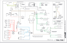
My problem or issue occurs when I turn on the ignition switch. The ammeter reading goes to the far end or "pegs" at the maximum reading for negative amps (-30AMPs). I am still able to turn over the starter when I push the starter button. The starter is a reduction gear starter and turns over as expected. Any suggestions on how to figure out what is causing this very high reading on my ammeter is greatly appreciated. Please note the lights work including dash, parking, and head lights. Horn works as well. My TR3A is set up for positive ground. Attached is a copy of the wiring diagram I am using.

Thanks,

Steve
 

Attachments

  • Screen Shot 2022-01-03 at 12.50.39 PM.png
    Screen Shot 2022-01-03 at 12.50.39 PM.png
    430.5 KB · Views: 198
Did you have extra wires in the lighting circuit? There are 3 extra wires in a new harness for side marker lights in Europe. The 3 wires are on the passenger side.
Not that I am aware of. Can you share where this wires are located on the harness? Engine compartment, rear of car? Thanks
 
Steve, the color coding for all the early BMC cars follow the same scheme. The brown and brown/with-stripe carry voltage. Apparently the fault is in the switch not contacting the green/red left-side leg of the harness. Could just be corrosion, or internal contacts worn or misaligned. Glad to find out the wiper motor is good, too.
Another more "graphic" wiring color code legend:

View attachment 75925
Thanks for sharing this Lucas color codes chart. Very helpful. In addition to the driver side parking lamps not working, the turn signals on the driver side are not working as well. Based on what is working and location, the next step is to check the control head wiring. Since the control head wiring is also original, might need replacing. I understand installing the new control head wiring in the stator (sp?) tube can be challenging, but is this case might be necessary.
 
In the engine compartment on the passenger side is where the 3 wires that are not used. They are green and red and green and brown. Two of them are hard to see in the pic, but you can see the double bullet connector that is empty if you look close, and the other is clear.

The heater wire is also in most new harness under the dash. It is a green wire that looks like it might go to the fuel gauge but is for the heater.

steve
 

Attachments

  • DSCN4617.JPG
    DSCN4617.JPG
    3.3 MB · Views: 95
In the engine compartment on the passenger side is where the 3 wires that are not used. They are green and red and green and brown. Two of them are hard to see in the pic, but you can see the double bullet connector that is empty if you look close, and the other is clear.

The heater wire is also in most new harness under the dash. It is a green wire that looks like it might go to the fuel gauge but is for the heater.

steve
Steve, Thanks for the addition info and photo. The 3 wires you describe I am aware of. I and have it set up as you describe. It was not clear as to why these double bullet connectors were used. Thanks for providing an explanation. One less item to worry about.

Regarding the green heater wire that is under the dash. Makes sense since the heater fan will need a power source. I did notice something that was not clear regarding a green wire under dash. This one green wire has a eye connector that is currently connected to the fuel gauge. This same eye connector has another green wire. I could not determine the purpose for this second green wire or where the other end of this second green wire connects. Is this the green wire you are referring to? Thanks again for your help.

Steve

Screen Shot 2022-02-15 at 11.25.23 AM.png
Eye connector
 
Not sure about the eye let, but I believe if the wire is green with no strip then that wire goes to the heater. You should be able to trace the green wire back to the fuse box. Moreover, I think the fuel gauge wires are green with a stripe. I thought perhaps you hooked up 2 green hot wires to each pole of the fuel gauge and was shorting there. Does your fuel gauge work? The other place there seems to be confusion is the wiper motor hook ups on the motor itself. I think some of the motors shut off when the ground is switched off plus on the side of the motor there a 2 different hookup that can be flipped . I would say double check the wipers and the fuel gauge.

steve
Steve,

Good point regarding the green wire I was referring to via the eyelet connected to the fuel gauge. I was able to confirm via the wiring diagram the green wire eyelet I was referring to connects to the fuel gauge and the other end of this green wire connects to the fuse box. The second green wire originating from the eyelet is currently not connected. Based on the wiring diagram for the heater, there is a green wire that connects to the heater fan rheostat/switch. I will see if the unconnected end of this green wire does connect to the heater reheostat/switch. Thanks again for your help with this.

Yes, both the fuel gauge and wiper motors are working. The wiper motor wiring hook-up was challenging at first. This was because I first used the wiring diagram from the Haynes manual that apparently is for the earlier, non parking, wiper motor. I most recently connected the wiper motor wiring using the wiring diagram I attached in my first message. The wiper motor now operates as it should.

My focus now is with the control head wiring. The control head is an area that is new to me. I did find previous posts/messages that cover replacement of the control head. It appears the most straight forward approach is purchasing a new control head that includes the control head wiring already attached. I mentioned when testing using the left turn signal, the ammeter measured very high current draw, greater than -30 amps. Also, the green/red wiring is dead on two ends of the wire (engine compartment side and rear turn signal). The connection point for the source of power comes from the green/brown wire where the connection to the red/green wire looks to be at the control head.

Thanks again for the help. You saved me a bunch of time and frustration regarding both the wiper motor and heater fan electrical hookups.

Steve
 
The control head could also be a short at the bulbs; they are all connected. You could unplug the control wires down at the steering box and then try each wirer one at a time to see which one shorts and then look at that bulb. The control head and stator tube should pull out and later go right back in when the wires are unplugged, and the brass nut for the stator tube is lose, and the grub screws are loosen at the steering wheel. you will lose some fluid from the steering box

The removal is straight forward. The steering wheel and everything stays in place. The grub screws could be stuck a little, so use some spray oil and a good fitting screw drive and they should come out.

After that you can decide, about your control head. They come apart into pieces, but are not really that difficult to take apart and put back together, lots of write-ups on it.

steve
Thanks Steve,

I appreciate the run down regarding best approach for removing and replacing the control head. I now understand that when removing the control head, the stator tube is also removed. This will make it easier in routing the new control head wiring into the stator tube.

Steve
 
I had the stator tube in place when I installed my control head. I threaded a piece of wire through the tube then removed the bullet connectors from the control head harness. The connectors will not fit down the tube,. Then attached the pull wire to the harness and carefully eased the wires through the tube. Did this with no assistance. A little pull then align the control head then another little pull. Repeat till the control head is fully home.

David
Stearing column wires.jpg
 
I had the stator tube in place when I installed my control head. I threaded a piece of wire through the tube then removed the bullet connectors from the control head harness. The connectors will not fit down the tube,. Then attached the pull wire to the harness and carefully eased the wires through the tube. Did this with no assistance. A little pull then align the control head then another little pull. Repeat till the control head is fully home.

DavidView attachment 76047
David,

Very helpful tip/recommendation. If better with the attached photo. Thank you.

Steve
 
Update regarding the new wiring harness replacement. There is one remaining item I am trying to resolve.

1) I have narrowed down the high current reading to be somewhere between the voltage regulator and generator. When I have the 2 wires connected to the generator is when the amp meter shows the excessive negative Amp reading (more than -30amps). When I disconnect the yellow wire from the D connector on the generator, this issue/reading adjusts to a correct reading (problem goes away). Looking for ideas on what might be the cause.

2) Highlights regarding my '58 TR3A electrical system: A) New wiring harness. B) Generator rebuilt Jan, 2021. C) Positive ground system. D) New voltage regulator. E) The recharging system was all working prior to replacing the hiring harness. Replaced the wiring harness was done because of a parking light wiring short (red wiring) problem.

I was thinking maybe there is a short with my generator but not really sure. My next step was to remove the generator and take it back to the shop that rebuilt the unit to see if they can test the generator. If you have any other recommendations, please let me know.

Also, all the other help provided in the earlier posts resulted in all other portions of my TR3 electrical working as it should. Thanks for all the help with this.
 
Last edited:
Back
Top