 but were afraid to ask:
When we were examining the clutch pedal, a wire must have come loose because the following are not functional: gas gauge, water temperature, wipers. heater and direction signals. All four fuses checked out ok. The only thing amiss was the flasher unit which was out of its holder. I did see that at least one other poster had the same problem but in his case, it was the fuse box. Can anyone give me a hint what to look for?
-
 Hi Guest!
You can help ensure that British Car Forum (BCF) continues to provide a great place to engage in the British car hobby! If you find BCF a beneficial community, please consider supporting our efforts with a subscription.
There are some perks with a member upgrade!**Upgrade Now**
(PS: Subscribers don't see this gawd-aweful banner

Tips
- We have a special forum called "Member Articles" where you can submit actual articles for consideration for publication. Learn More
- Don't have an Avatar? If not, your avatar will default to the 1st character in your username. Go into "Account Details" to change your Avatar.
- Some basic forum navigation info: click
 Hey - did you know if you click on the title of a thread it will take you to the first unread post since you last visited that thread?
- Hey Guest - Is your British Car Club in our Clubs database? If not, send me a PM - Basil

- Looking for a local club? Click the "Clubs" tab above and browse hundreds of clubs world-wide.
- Add Android or iPhone APP: click
- Did you know - any picture or video you add in your posts in any marque-specific forum will also get added to the Media Gallery automatically.
- A few more tips about posting and replying: click
- Hey there Guest - be sure to keep your profile page up to date with interesting info about yourself: learn more
- More tips and tricks on Posting and Replying: click
 STOP!! Never post your email address in open forums. Bots can "harvest" your email! If you must share your email use a Private Message or use the
  smilie in place of the real @
- Want to mention another member in a post & get their attention? WATCH THIS

- So, you created a "Group" here at BCF and would like to invite other members to join? Watch this!
- Hey Guest - A post a day keeps Basil from visiting you in the small hours and putting a bat up your nightdress!
- Hey Guest - do you know of an upcoming British car event?
 Pretty Please - add it to our Events forum(s) and add to the calendar! >> Here's How <<
- Hey Guest - you be stylin' Change the look and feel of the forum to fit your taste. Check it out
- If you run across an inappropriate post, for example a post that breaks our rules or looks like it might be spam, you can report the post to the moderators: Learn More
- If you would like to try some different "looks" or styles for the site, scroll to the very bottom, on the left and click the Style Selector.
You are using an out of date browser. It may not display this or other websites correctly.
You should upgrade or use an alternative browser.
You should upgrade or use an alternative browser.
TR6 Electrical Problem
- Thread starter pdplot
- Start date

Offline
See arrow:

PS - color wiring diagram (everyone should have one - NFI) for USA '74 TR6 from Prospero's Garage:
www.colorwiringdiagrams.com
PS - color wiring diagram (everyone should have one - NFI) for USA '74 TR6 from Prospero's Garage:
www.colorwiringdiagrams.com

Offline
Thank you for the link. I am a long way from wiring but as items like this are brought up I make a note of it for my Christmas list. I know this will come in handy down the road. Frank
poolboy
Yoda
Offline
The book that one day you'll be happy you have it or the day you wished you did.
https://mossmotors.com/electrical-maintenance-handbook
"pd" that connection shown in the schematic is in a place none of us like to go....under the dash, near the firewall, but what I don't remember is if it's a plug or a splice in the harness. The symbol in the schematic indicates a splice, but that's not always the case. I hope its a plug and you can spot it.
I used a test light on the fuse box. Black test wire to ground battery terminal.Top fuse block (1) to bottom (4 1 - no light. 2 light with key on or off. 3 -light with key on. 4 - no light. Fuse 4 has a double red wire going in. I have the Bentley manual with the wiring diagram but it's tough reading - I have to use a magnifying glass to read the colors. I should have gotten the Moss manual or the Masters manual but to tell the truth, since the first months of ownership in 1995, I've had no electrical problems whatsoever other than a couple of burned-out bulbs. I read that if its only the two gauges, then the voltage stabilizer is bad, but three other things are also out so its got to be in the wiring. I'll look in the manual to see what fuses 1 and 4 are used for. Thanks for the readable diagrams.
1 - no light. 2 light with key on or off. 3 -light with key on. 4 - no light. Fuse 4 has a double red wire going in. I have the Bentley manual with the wiring diagram but it's tough reading - I have to use a magnifying glass to read the colors. I should have gotten the Moss manual or the Masters manual but to tell the truth, since the first months of ownership in 1995, I've had no electrical problems whatsoever other than a couple of burned-out bulbs. I read that if its only the two gauges, then the voltage stabilizer is bad, but three other things are also out so its got to be in the wiring. I'll look in the manual to see what fuses 1 and 4 are used for. Thanks for the readable diagrams.Tr6easyrider
Senior Member
Offline
These might help.
http://www.advanceautowire.com/tr2506.pdf
http://www.advanceautowire.com/tr2506.pdf
How I wish I had a color printer. Or some crayons. Thanks for the help. Bad back and old age prevent me from laying under the dash so it will have to wait until the weekend. I will use a mirror and a camera to check for a loose wire. Finding an open circuit or worse, a short that keeps blowing fuses is tedious and time-consuming. One of the worst jobs on these cars. Made especially hard on my car because a DPO sprayed the engine compartment with black paint and didn't cover the wires - so they're all black and I have to carefully scrape the black paint off.
Offline
Using a VOM meter to trace the wires will come in handy.
Offline
How I wish I had a color printer. Or some crayons.
Take it to Fedex/Kinkos or the like, and have them print and laminate one for you.
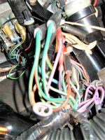
I did have a green pen, a red pen, a blue pen and a black pen. Filled in the lines with the correct colors. Purple was a problem but I wrote it out. There are two loose wires under the dash but they may have been there all along. Blue and white and purple and red. I think they may have been for the seat belt buzzer and the tunnel light. Everything else looks good under there. Continuity in the fuse box. There appear to be two junction boxes mounted to the inner fender flanking the fusebox. What are they? Pictures attached.


Attachments
I'm beginning to think the problem isn't on the hot side but the ground. He may have knocked off a ground wire while bleeding the clutch. Where does the green circuit ground wire attach? The wiring diagram only shows the black ground wires but not where they run to.
There is a ground tab there but it looks like it has never been used. No ground wire in sight. Its right near the bundle of wires coming out of the firewall running down to the starter. The ammeter and oil pressure gauges work, the lights and horn work as does the radio and my interior lights on the tunnel. Everything was working perfectly before he bled the slave cylinder and detached the clutch pedal. As I stated, since fixing the initial shorts 25 years ago, the electrical system has worked perfectly. What could he have done to cause this? Or is it just a coincidence?
This thread is probably dead by now, but it looks like like all of the components that aren't working involve the green wired fused circuit. On my 71, there is a bullet connection that connects all of the culprits together. It should be under the dash. Also, the fuse could be good, but the fuse holders might be corroded where they are connected to the space terminals. The riveted connection could be the culprit. Good luck.
Berry
Berry
You are correct about the green circuit. Although it may be bad for my health, I'll try to crawl under and see if there is a disconnect. There is nothing hanging down except for a couple of dead wires that were disconnected many years ago. Until I find the problem, this thread is far from dead...all contributions cheerfully accepted.
The book that one day you'll be happy you have it or the day you wished you did.
https://mossmotors.com/electrical-maintenance-handbook
"pd" that connection shown in the schematic is in a place none of us like to go....under the dash, near the firewall, but what I don't remember is if it's a plug or a splice in the harness. The symbol in the schematic indicates a splice, but that's not always the case. I hope its a plug and you can spot it.
I'm going to show this to my uncle tomorrow. I'll be coming over to help him install the headache rack and hard tonneau cover on his current truck project. I guess we will that eletrical handbook sooner or later.