• Hi Guest!
    You can help ensure that British Car Forum (BCF) continues to provide a great place to engage in the British car hobby! If you find BCF a beneficial community, please consider supporting our efforts with a subscription.

    There are some perks with a member upgrade!
    **Upgrade Now**
    (PS: Subscribers don't see this gawd-aweful banner
Tips
Tips

Directionals, Still a Pain

Ray,

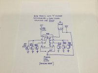
You are doing great work. As I suspected, my descriptions are perhaps not that great. I decided to draw a quick circuit diagram to depict your configuration (as it should be) with the “P” disconnected and the dash bulbs grounded on the “P” side instead. I have attached the picture below:

The circuit depicts your circuit as described and assumes for example the right hand turn signal is selected. As you can see, there is NO VOLTAGE at FRB terminal #6 when turning right. The only voltages that should be present at the FRB are at terminal #1 (from the flasher “L” terminal), at terminal #4 (from the steering wheel switch) and this voltage at #4 swings the arm at terminal #3 across to short terminals #1, #2, and #3 together. This provides the flashing “L” voltage from terminal #1 to #2 and #3 which applies the voltage to all three right hand bulbs.

So, and this is important, if your design and wiring of your FRB is in accordance with the original phase 1 design and working as the original box did, there cannot be voltage at #6 when you select a right turn and hence nothing at the left dash bulb. I can only conclude there is an issue with the build or installation of your FRB.

Best of luck on your quest.

Cheers
Tony
 

Attachments

  • 45663A78-CF9C-44E8-B686-3E2C091421F8.jpg
    45663A78-CF9C-44E8-B686-3E2C091421F8.jpg
    32.3 KB · Views: 99
Ray,

Minor addition, I just checked my workshop manual and it shows terminals #2 and #3 operate the left and terminals #6 and #7 operate the right, but it doesn’t matter which way you wire it as long as you are consistent.

Cheers
 
Hi Tony,

I was finding it difficult to describe the original wiring of the directional signals (including the Dash indicators) and decided to clear my thoughts through a picture. The diagram posted is a Pictorial of a Right Turn executed through the Original 3 terminal Flasher circuit and the same turn under a 2 terminal Flasher configuration. You will note that I have included Ground paths for the signals and Dash indicators as this area of the circuitry can be quite confusing.

Directional Signal Circuits, Operation, and Modification.jpg

As you can see from the diagrams, under the original configuration, both Dash indicators are provided power simultaneously through the "P" terminal of Flasher. However, the opposite side of each Dash Indicator Flasher "P" Power connection is also connected to the FRB #6 Right Turns/#2 Left Turns to also direct power to the non-selected side in order to eliminate access to a ground. Keep in mind that, as you have described, power is only supplied on the selected side and the opposite FRB terminals are disconnected from power but with the circuit completed to Ground. As a result, by applying power from the Flasher to the Non-Selected Dash Indicator from one side of its Bulb circuit and Power from the Selected FRB side or terminals #6 or #2 on the other side of the Bulb circuit, the bulb is starved of a Ground. However, on the Selected side, Power is also provided to the Directional Indicator from the Flasher "P" terminal on one side of the Bulb circuit and NO Power from the FRB (no power present) to the other end of the circuit and the Ground is now allowed to pass and turn on the bulb.

This is one of the most frustrating and confusing projects I have undertaken. Not because it was so difficult but because of the placement and consequential damage caused as a result of the placement of targeted components (the last was a broken costly plastic dash arrow).

I really appreciate your council in this task and expect we will be continuing our long distance collaboration.

All the best,
Ray(64BJ8 P1) Since New
 
Last edited:
Ray
it looks like the off-side dash light had power coming from both ways which kept it from lighting, no electron flow, like the ignition light with the engine running.

guessing there was not enough wire at the relay to just switch the wires there and leave the dash lights alone for your fix.

either way sounds like you got it.
 
Hi All,

Ray
it looks like the off-side dash light had power coming from both ways which kept it from lighting, no electron flow, like the ignition light with the engine running.

This was a very confusing and, at times, aggravating project with many unexpected issues and little information. I am not sure what went wrong as others have rebuilt their Flasher Relay Box with no changes to the operational integraty of signaling systems. In my case, the actual turn signals and brake lights performed as expected with only the Dash Indicators (DI) giving grief. As originally configured, I now think that somehow the Right turn DI just couldn't find a path to the its ground and, in its search, caused other components to be affected. This winter I will continue my search for the issue and, finding and rectifying the issue, return to the original 3-contact Flasher configuration.

Originally, I was under the impression that the DI circuit was configured to reflect any issues in the external signal lights (as in modern cars). Since each DI ground seems to only pass through the front external signal light on the opposite side selected, I now don't think this is the case and have no idea why the system was made so obtuse. Since I pride myself in having every Healey change made to be reasonably reversible, I will also make sure that all the conditions met by the original are also reflected in the circuits of the rebuilt system.

It is Questionable whether I would recommend this project to others. As in many published Healey changes, there is always some level of uncertainty and non-disclosure. This was definitely the case with this project. Removal of the Box required access to the 2 upper screws which required the removal of the Cold Air Duct, which required the removal of the left front fender, which required the removal of the Door. Also, access to the box required the removal of the front Carburetor Air Cleaner and access was still incumbered by being behind the brake reservoir and gas line. Additionally, with my DI problems, I had to get under the dash which meant sliding under the steering wheel (no problem in my younger years but now …). Although I would rather Fix or Create then acquire a replacement (as does Steve), in this case modifying the Flasher Relay Box was the easy part and all the trials and tribulations would have been experienced whether the box was fixed or acquired. Additionally, it may have been a more expedited project had I just taken the BJ8 Phase 2 approach and used the installed lights behind my reflectors as dedicated Directional Signals thereby eliminating the necessity for the Flasher Relay Box.

Well, those are my thoughts and I hope others find benefit,
Ray(64BJ8P1)
 
Last edited:
Hi All,

After modifying the dash directional circuitry by adding grounds to each light and flipping the bulbs/indicator-circuits sides-to-side (as described in a previous post), all performed even better then with the original Flasher Relay box in good working condition. During the process, however, I broke the right hand plastic of the original dash indicator and acquired a new unit. Although the appearance of the part received may have been OK if I had replaced both, the new dash directional indicator fell short of reflecting the quality of the original and, when viewed in person, dramatically presents this deficit.

Dash Directional Indicators
For some reason the picture seems to download up-side-down with the NEW Right Turn Indicator on the left and the Original Left turn Indicator on the right. As you can see, the new replacement has a duller metal cover with a slightly smaller arrow.

All in all, this project is now functionally completed and I have operational Directional/Brake Signals. However, for those who will need to address this issue and choose to rebuild their FRB (as I did) or acquire a replacement, I trust those reading my posts will be somewhat prepared when encountering the problems of box access.

All the best to all,
Ray(64BJ8P1)
 
Last edited:
Back
Top