Hey Guest!

 Hey - did you know if you click on the title of a thread it will take you to the first unread post since you last visited that thread?
 but were afraid to ask:
  STOP!! Never post your email address in open forums. Bots can "harvest" your email! If you must share your email use a Private Message or use the
  smilie in place of the real @
 Pretty Please - add it to our Events forum(s) and add to the calendar! >>
Keoke
Great Pumpkin
Offline
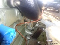
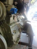
Be careful here a lot of parts on these cars were steel copper plated.
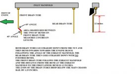
Roger if the lines were not Z shaped you would incur vacuum leakage.
A P trap is not required here because it is not fuel trapped in the line like home plumbing it is the air loss created by the line's shape and length.
Yes Johnny,, you are correct about how and where the lines terminate requiring the bends.