• Hey Guest!
    British Car Forum has been supporting enthusiasts for over 25 years by providing a great place to share our love for British cars. You can support our efforts by upgrading your membership for less than the dues of most car clubs. There are some perks with a member upgrade!

    **Upgrade Now**
    (PS: Upgraded members don't see this banner, nor will you see the Google ads that appear on the site.)
Tips
Tips

Continuity mystery

M

Member 10617

Guest
Guest
Offline
I am looking into replacing some odd wiring on my TR3 from the regulator to the generator.

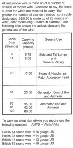
There are two wires, as most of you know: a yellow wire from "D" to the main generator terminal (yellow pvc, 28 strand), and a yellow/green wire from "F" to the field terminal on the generator (yellow/green, 14 strand).

Here is the problem and the mystery. The yellow and yellow/green wires lead from the control box and disappear in the tape-enclosed harness. When the wires emerge from the harness on the way to the generator, they are both black wires (I believe someone spliced in new wires when the old generator was replaced with a new one and did not use the properly coded wires).

Being very close to the exhaust these wires have suffered greatly from the high heat and could stand replacement.

Mystery: I checked the continuity between the "D" terminal on the control box and the main generator spade terminal to make certain I was looking at the proper wire and got a continuity signal. But, I also got a continuity signal when I left the probe on "D" and touched the field terminal on the generator with the probe (!!).

How can that be if there are two separate wires running from "D" and "F"?

I am thinking of disconnecting the wire that links "D" and the main generator terminal and running a new, properly coded, wire directly from "D" to the main generator terminal, and the same thing from "F" to the field terminal, entirely bypassing the old wires and harness, leaving the old wires in place but disconnected for the time being.

Any idea why I would get continuity from "D" to the generator termonal AND the field terminal? Any thoughts on running wires directly from the control box to the generator (outside of the harness)?

I hope I've described all this accurately...
 
Ed,

"Continuity" is a very slippery concept, and can lead you dangerously astray.

In this case there are two paths that link the two wires together. Inside the regulator, with the engine off, the voltage regulator contacts connect the F and D terminals together. But you would likely get a continuity reading even with the wires disconnected from the control box; because they are both linked to ground within the generator.

In short, the only reliable way to check continuity is with both ends disconnected.

Originally, the two wires to the generator were only in a sub-harness of their own. They should not run through the main harness at all. There is no harm in running two separate wires as a replacement for the 2-wire subharness; but personally I would want to add some protection to them since having either one short to ground will result in sparks, disabling the generator and likely doing permanent damage to the control box (and possibly generator). I generally use black poly braided sleeving: https://www.mcmaster.com/#standard-cable-sleeving/=jz7lxc
then secure the cut ends with heat shrink tubing
https://www.mcmaster.com/#electrical-heat-shrink-tubing/=jz7nmq
Here is a small sample of the result:
DSCF0029_crop.jpg


There are lots of other methods of course.
 
Randall,

Great information. When I tried to check the continuity, I disconnected the wires from the generator, but I didn't disconnect them from "D" and "F." So, as you said, the regulator contacts kept them connected gave me "continuity" at the ends of both wires (!)

I undersand it clearly now.

As soon as I receive the proper spade connectors from British wiring, I will prepare the two new, properly coded, wires to run from "D" and "F" and put them outside the main harness, but in a sub-harness as you suggest. I have heat shrink tubing and will use it on the ends of the sub-harnesses.

As I have found in the past, figuring out the proper gauge/strands for TR3 wiring can be mysterous to the inexperienced like me. The wiring diagram gives the color codes -- for tracing purposes -- but not the gauges/strands of wires. I had to call Josh at British Wiring for the information on the wires to the generator and he kindly let me know so I could order the proper wire. I wish there were some chart showing all this. The only thing that comes close (that I know of) is the LUCAS Technical Service, Overseas Technical Correspondence Cource, Section 6: Vehicle Wiring Circuits, which shows:

"There are five sizes of cable altogether in general use on the 12 volt system, but for most purposes three are commonly used. These are :--

1. The battery feed circuit cable, comprising 44 strands of .012 copper... This cable has the current carrying capacity of approximately 22 amperes.

2. Main generator or head lamp circuit cables, comprising 28 strands of .012 copper... with a current carrying capacity of 14 amperes. For most purposes this is adequate.

3. Side and tail lamp wiring, accessory, ignition and generator field circuits comprising 14 strands of .012 copper... with a current carrying capacity of 7 amperes.

4. For panel lamp wiring and other incidentals a cable comprising 9 strands of .012 copper ... is the most convenient size."


Of the various sleevings available, would you chose:

1. High-Temperature Expandable PEEK Mesh sleeving?

2. High temperature fiberglass sleeving?

3. Ultra-High-Temperature Silica Sleeving?

4. Ultra-High-Temperature Ceramic Sleeving?

or 5. High-Temperature Abrasion Resistant Kevlar-Reinforced Fiberglass Sleeving?? (Can I even cut this Kevlar to length?)
or some other? Polyester? Polyethylene? Polyurethane?

Fixed diameter or wrap-around?
 
To be honest, Ed, I just use the ordinary poly expandable mesh sleeving that I have on hand.
(Maybe this link will work right, sometimes the MMC web page doesn't want to cooperate.)
https://www.mcmaster.com/#catalog/118/817/=jz9hjl

But if you wanted something better able to handle the heat from the manifold, I'd suggest the expandable mesh PEEK sleeving. There is really no point in using something with a much higher temperature rating, since your wire is still (I assume) going to have PVC insulation. And the fiberglass sleeving is rather unpleasant to work with, IMO.

Yes, you can cut the Kevlar-reinforced stuff to length. Just use some good heavy scissors or shears (not your wife's good sewing scissors). The cheap ones they sometimes give away at HF should do fine.

Sorry, I'm not much help on the 'correct' wire sizes. I would probably use 12 AWG for the generator output and 16 AWG for the field, but I have a definite tendency to go overboard on wire sizes. Thinner wire may not overheat from the amount of current, but it will definitely deliver less voltage to the load (although the difference may not be enough to worry about). Thicker wire is also stronger, so is less prone to break.
 
Randall,

My thought is that I'd like the new harness/sleeving to protect the wire from the high heat from the manifold. It's the heat that has almost done in the wires that are there, just about an inch away from the manifold.

I will go with the expandable mesh PEEK sleeving. Yes, the wire I have from British Wiring has PVC insulation, so the combination should keep things reasonably cool down there.

As for the gauge/strand question, I have no expertise at all on this. I'm simply going on what the LUCAS book recommends and, better still, what Josh at British Wiring said I would need. As you know, the 28 strand is equivalent to 14 AWG, and the 14 strand is equivalent to 18 AWG. Why when the number of strands of British wire goes up the US gauge goes down is another of those mysteries to me.... It's just "a British thing."

As usual, many warm thanks. I hope this helps others in the same boat.
 
LexTR3 said:
As you know, the 28 strand is equivalent to 14 AWG, and the 14 strand is equivalent to 18 AWG.
Only roughly, they are not actually the same size.
<div class="ubbcode-block"><div class="ubbcode-header">Quote:] Why when the number of strands of British wire goes up the US gauge goes down is another of those mysteries to me.... It's just "a British thing."[/QUOTE]
Counting strands is reasonable enough, for stranded wire and if you assume the strands are all the same size.

AWG is actually a solid wire measurement, originally related to the number of drawing operations used to form the wire. Each drawing would reduce the size of the wire, hence the more drawings the smaller the wire.

As you say, just one of those things, kind of like inches and millimeters.
 
To thoroughly confuse matters, I have received the attached wire chart. By calling for 44 strand wire for the generator and control box, it contradicts the LUCAS technical manual's call for 28 strand wire for the main generator circuit and 14 strand wire for the generator field circuit. Isn't 44 strand a bit unncessarily heavy for the control box-generator connection?
 

Attachments

  • 30010.jpg
    30010.jpg
    87.7 KB · Views: 235
LexTR3 said:
Isn't 44 strand a bit unncessarily heavy for the control box-generator connection?
I don't think so, obviously, since that is essentially what I recommended above.

Note please, that the antique Lucas document you referenced originally mentioned "with a current carrying capacity of 14 amperes". Perhaps that was adequate for the generators they had back then, but the stock generator for a TR3 can put out 19 amps continuously (if the load is high enough or the battery is deeply discharged). And it is very common for it to be replaced (often without the owner even realizing it) with the later C40/1 unit that can put out 22 amps continuously. In both cases, the output may go even higher for a short period just after starting the car (while the voltage regulator is still cold).

Also, the generator output lead lives in an area that gets quite hot. Wires need to be derated when used in hot environments, because it leaves less margin for the wire to heat up (from the current) before the insulation starts to degrade.

Something else that might not have been clear: When the sleeving says it will "withstand" a certain temperature, it just means that the sleeving itself will not melt or burn at that temperature. It says nothing about keeping the wire inside "cool" and may even let the wire get hotter than it would without the sleeving.
 
For what it's worth - my recently purchased 59 TR3a's original equipment generator would not charge. Initially it was a stuck cut-out relay in the control box or voltage regulator. But then it quit again. To remove the generator for testing I slid back the protective 2" long black sheathing on the large, main generator terminal connection to discover that under that protective sheathing, the wire just had a bare end, 1/2" long, taped sideways to another piece of bare wire, 3/8" long, that had been soldered to the main generator terminal. The two short pieces of bare wire were not even twisted together. This less than perfect connection caused the whole problem. Using my old Weller soldering gun I desoldered that short piece from the generator's spade terminal which then measured 3/8" wide. At our local Auto Zone parts store they had a single pack of 3/8" wide, insulated, slide on, friction fit, crimp type connectors for #12 - #10 wire, stock # 85447, for a little over $3.00. They fit perfectly with a firm friction fit and the stranded wire also fit perfectly in the crimp-on connectors opening. I crimped one of the connectors to the bare end of the wiring harness, carefully wiggled it on, and I now have 13.5 volts coming out of that generator at 1800 RPM. It's little things like this that drive you crazy. Hope this helps.
 
Good tip on where to buy those quick connects. Radio Shack used to carry them, but no longer.

However the earlier generators used ring terminals, not quick connects. More of a pain to R&R, but also more secure IMO.
 
Randall,

In fact I have a new generator on the car, and the information on wire (strands) did come from an old LUCAS technical manual (when the older generator was in use).

You have made a very good case for using 12 AWG (44 strand) wire for the main generator circuit in my "upgraded car" and 16 AWG for the field circuit.

I don't see the "strand" equivalent to 16 AWG anywhere. Could I substitute 14 strand (18 AWG)?
 
Sure, Ed, 14 strand would work fine for the field circuit.
 
Randall,

Great. I will modify my plans and use 44 strand for the main generator circuit and 14 strand for the field circuit.

As soon as I receive a crimping tool I have ordered and some new female spade connectors, I'll get to work on this project.

Thank you very much for you good advice on this.
 
Randall,

As you know, the wire that goes from "D" on the voltage regulator (control box) to the main generator terminal also goes to the Ignition Warning Lamp. At present, both wires are 28 strands. If I change the wire from "D" to the main generator terminal from 28 strands to 44 strands, do I also have to upgrade the wire that goes to the Ignition Warning Lamp to 44 strands, or can I leave it at 28 strands?
 
LexTR3 said:
Randall,

As you know, the wire that goes from "D" on the voltage regulator (control box) to the main generator terminal also goes to the Ignition Warning Lamp. At present, both wires are 28 strands. If I change the wire from "D" to the main generator terminal from 28 strands to 44 strands, do I also have to upgrade the wire that goes to the Ignition Warning Lamp to 44 strands, or can I leave it at 28 strands?
You can leave it. Actually, my recollection is that it was not 28 strand to begin with, but whatever is there is fine. The light draws much less than 1 amp.
 
Randall,

THANK GOODNESS!! The wire from "D" goes through the firewall and into the harness and then into the spaghetti mess of wires behind the dash. It would be almost impossible for me to replace that wire.

Again, many, many thanks.
 
If it isn't one thing... it's another.

The female spade terminal connector on the end of the wire that connects with the main generator male connector is 3/8" and fits fine. I have a new one for the new wire I intend to install, and it is 3/8" also. But it doesn't fit over the male connector -- too tight.

Is there some proper/effective way to spread the female connector a bit to make it fit?
 
Randall's right about the ring terminals he mentioned. They are a better connection. More secure and with greater surface area against the generator male terminal. I used the friction fit slide on 3/8" connector on my generator connection because it was quick, had a nice tight fit and the late October weather was great for driving a TR3, which I was really wanting to do. But I will eventually convert to a ring terminal crimped and soldered to the generator wire, covered with heat shrink tubing and then secured to the main generator terminal with a #6 or #8 screw and one of those slightly deformed nuts that will not vibrate loose. Not the plastic insert but a stainless steel deformed nut and bolt. I might even consider soldering that too for long term corrosion protection. Another option I am considering is soldering a 8-10" long pigtail to the generator terminal, covering the terminal with heat shrink tubing and connecting the pigtail to the wiring harness with two more bolted together ring type terminals, or the a male/female combination of the friction fit, round, plug type terminals also covered with heat shrink tubing. I think this last option would make it easier to remove the generator without disturbing the wiring.
 
Tcraftdriver,

I have read your interesting ideas about how to better secure the wire to the generator but I am having trouble picturing what needs to be done. The generator male terminal on my generator is a flat, 3/8 inch blade with no hole in it. How would I secure the ring terminal with a #6 or #8 screw and "deformed" nut to the generator male terminal?

With some effort, I should be able to widen the female spade terminal just a little in order to fit it on the male terminal. One possibility is to purchase a 3/8" male spade terminal, secure it in a vise, and force the female terminal on and off until it goes on a little easier.

Another possibility would be to put the tight fitting spade terminal on the main generator male terminal and plan to leave it there. Then, several inches up the wire to cut the wire and splice it back together with bullet connectors. The bullet connectors are pretty secure, and snapping them apart if I have to would be easier than trying to wrench the female spade terminal off and possibly injuring its connection to the generator.
 
LexTR3 said:
I have read your interesting ideas about how to better secure the wire to the generator but I am having trouble picturing what needs to be done. The generator male terminal on my generator is a flat, 3/8 inch blade with no hole in it. How would I secure the ring terminal with a #6 or #8 screw and "deformed" nut to the generator male terminal?
Drill a hole in the terminal.
<div class="ubbcode-block"><div class="ubbcode-header">Quote:]Another possibility would be to put the tight fitting spade terminal on the main generator male terminal and plan to leave it there. [/QUOTE]
My experience has been that they tend to loosen over time anyway; so my approach would be to open it up just enough (with a small flat blade screwdriver or similar) that it can be installed without risk of damaging the generator; then leave it that way (without any additional connections). I would probably also add some heat shrink tubing around the outside of the connector, both to help protect it and to reduce the chances of a short.

The way I see it (and the electronics industry as well), every interconnection reduces reliability by some amount. And after all, if necessary you can just take the two wires loose at the control box and remove the generator with its subharness still attached.
 
Back
Top