• Hi Guest!
    You can help ensure that British Car Forum (BCF) continues to provide a great place to engage in the British car hobby! If you find BCF a beneficial community, please consider supporting our efforts with a subscription.

    There are some perks with a member upgrade!
    **Upgrade Now**
    (PS: Subscribers don't see this gawd-aweful banner
Tips
Tips

TR2/3/3A Beginning the TR2 Bodywork

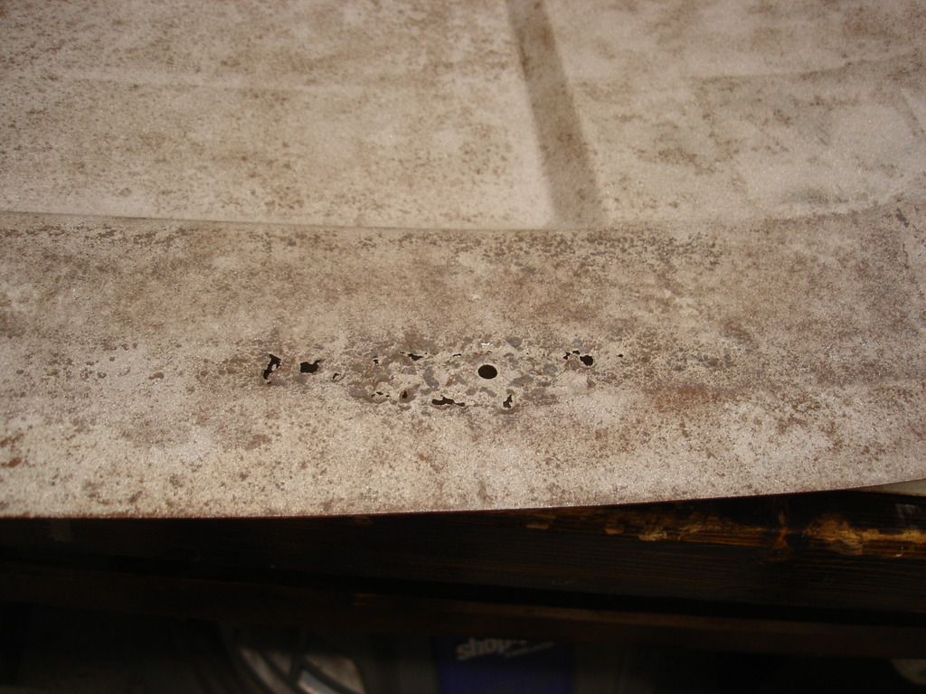
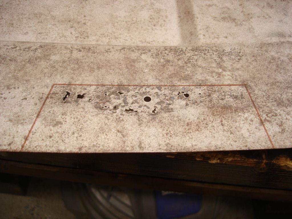
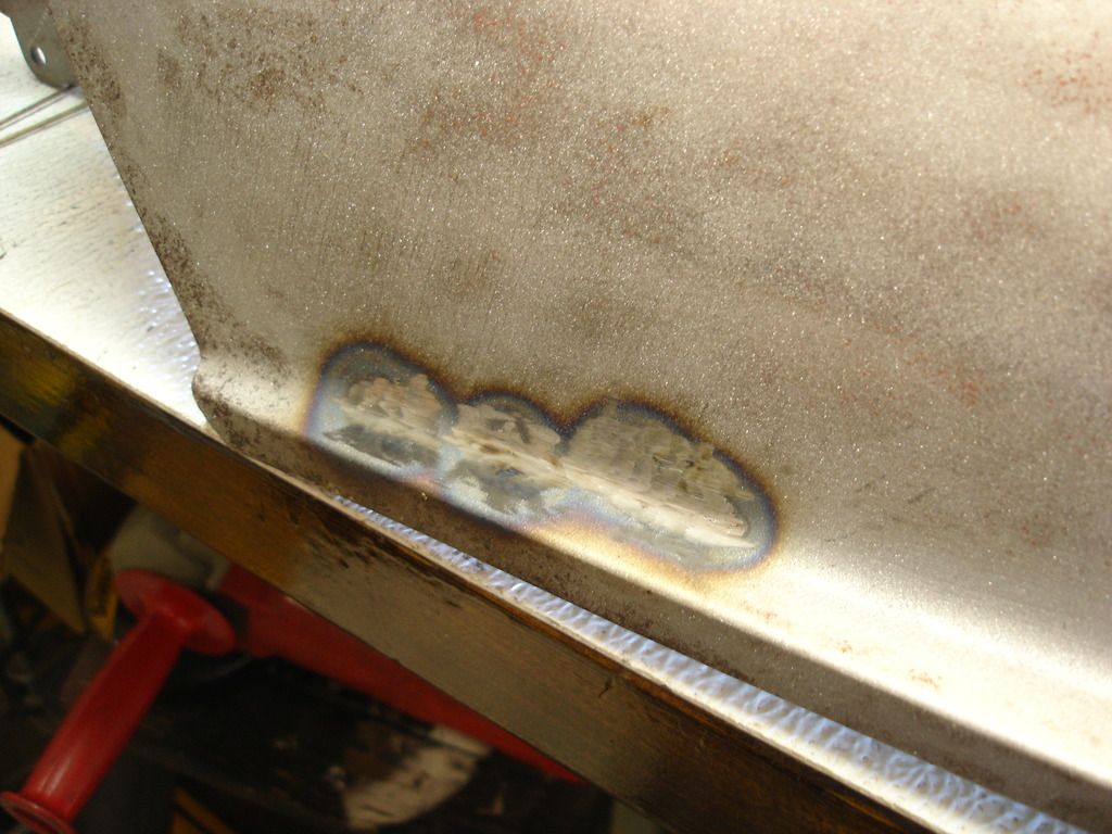
Great examples John. I feel like I've had to do all that metal work on my TR over about 18 months of welding, grinding, patching, etc. For oil canning, I work small areas with my oxy acetylene torch and then hammer and dolly. It's amazing how even though you are striking the area, it shrinks up tightens the metal so well. I've also used a wet rag at times, which works pretty well. When I welded the sides of my new floor pans, the floor pan oil canned horribly (Shrunk around the perimeter, as you'd expect). I spent about an hour with the torch, hammer and dolly, and sometimes wet rag and the floor tightened right up and no more oil canning. Was great.

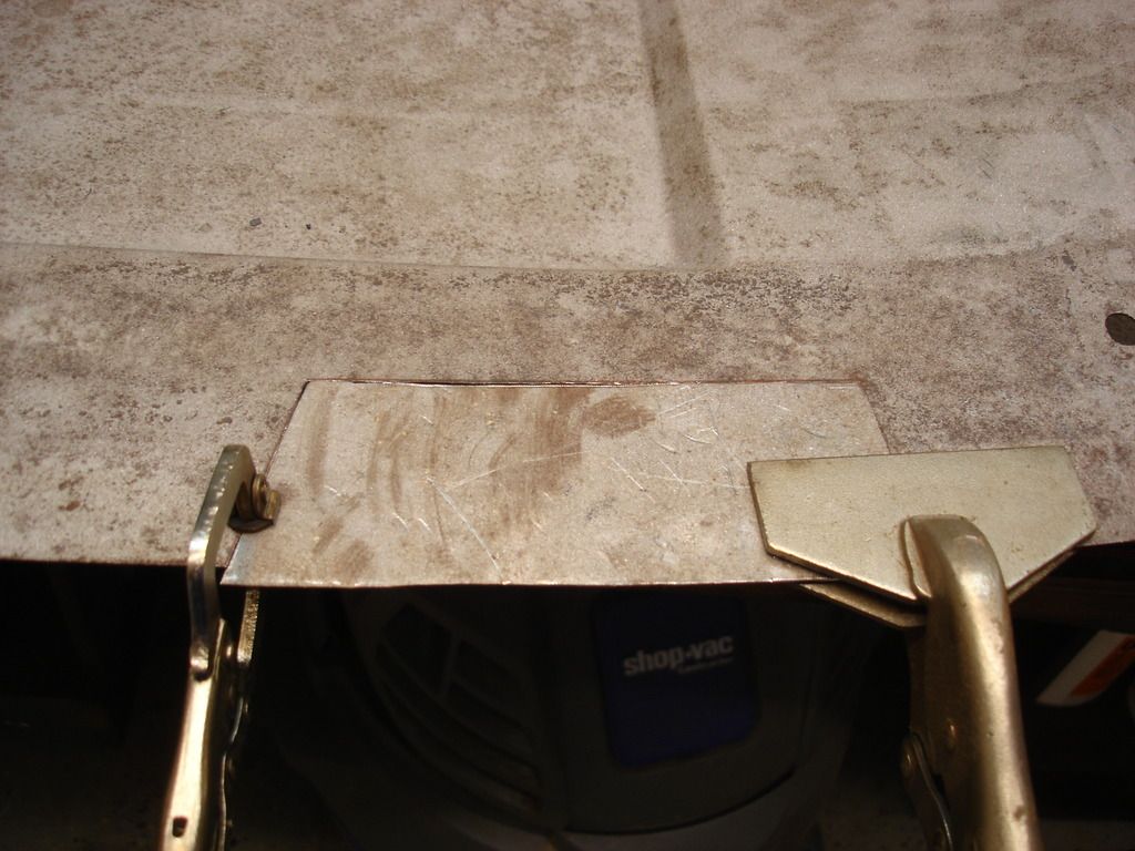
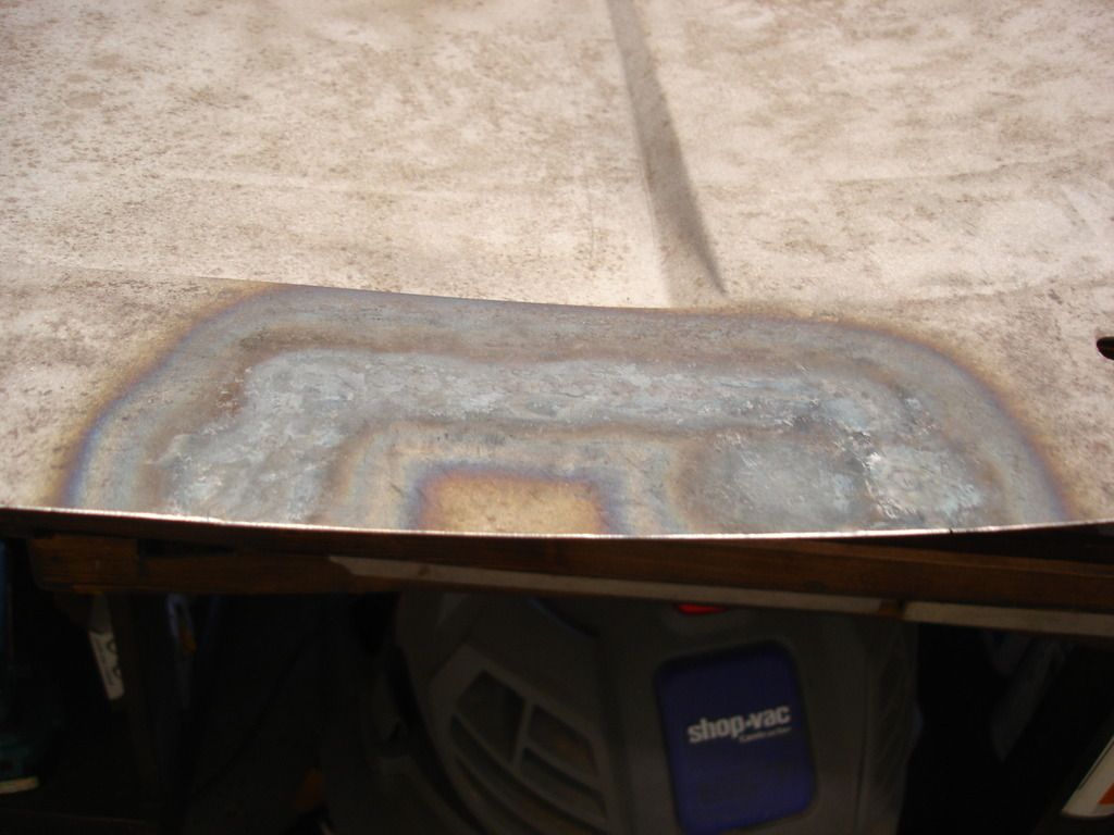
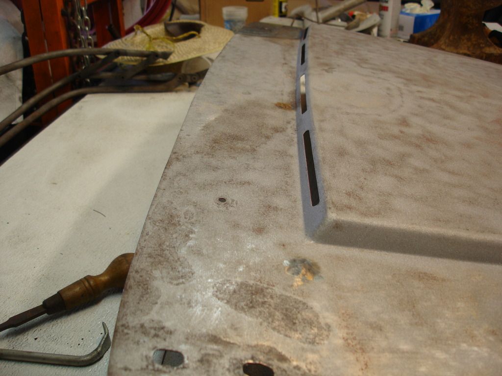
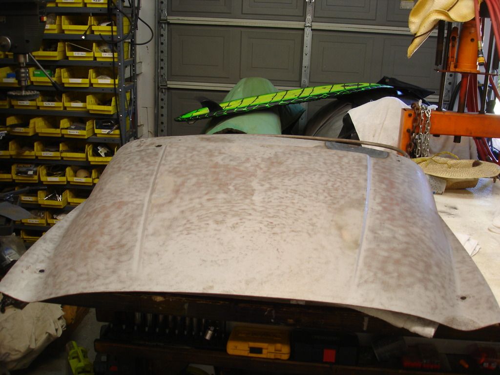
Towards the end of my metal work, I obtained a stud welder and used the shrink tip on that with compressed air to shrink areas. I welded a patch panel on the lower front wing, in front of the door. The long lap weld on the patch panel caused the panel to shrink horizontally on the panel area and the fender oil canned badly. With the stud welder shrink tip and the compressed air, I could quickly shrink the "fat" areas and tighten up the panel. I really enjoyed how easy this was. I realize if I had butt welded the patch panel, I could have hammer and dollied the weld and stretched the panel horizontally, maybe removing the oil can. With a lap weld, the metal is double thick and you can't stretch it without a BFH and probably panel damage. I would do it differently now, but the oil can example still holds (for the enjoyment of the esteemed forum members). Lap welding patch panels is easier, but not without it's own problems.

I think the key is always to analyze the panel and think about where it needs to shrink and where it needs to stretch, to meet your desired contour. And take your time.

Pat

 
Pat, I love learning about cool tools. If you get a chance, could you show us all how the shrink tip works with the stud welder?
 
Week 7

It's been 2 weeks since my last installment. I'm afraid the holidays are near, so my work is slowing. From here until the New Year I may stall out...we'll see!

Rusted Panel Repair

Before I get started with replacing rusted out metal...I need some metal to use for the patches. I have been saving all the unused body panels, so here is my patch material:


The lower edge of this old door skin is rusted, but the rest of it is just fine.


There are many ways to cut metal for patches. For what I am doing today, I will use just simple aircraft tin snips. The green is a right cut, and the yellow is a straight cut. Red handles are for left cutting. I show these just so all realize there are different "hands" when it comes to snips, so you won't beat your head against a wall one day trying to figure out why you can't get a good cut in one direction or the other.


Here's the first section to be replaced. It is along the edge of the apron. Simply cut out the bad metal.


Now I straighten the edge, as the shears tend to mangle it a bit.


To mark the shape of the replacement metal, I use a carbide tipped metal scribe.


You can just see the marks for the cuts to be made.


Frequently before and after cutting, I needed to re-flatten the parts, so they have a good fit.


And here is the finished tab ready to weld into place.


This is a quick look at an auto shade welding mask. I can't believe I worked without one of these for 30 years!!


I start with an initial tack. I attempted to clamp the piece in place, but gave up with it's small size. I just lined it up by hand and tacked.


I continued to line up the edges perfectly and adding tacks. Every so often you have to pull out the hammer and dolly to flatten the work out. When you tack, the tack contracts as it cools...and that tends to distort your alignment. Simply hammer the tack against the dolly, and it "stretches" it back out straight.


Now I start running the welds in 1 second bursts, allowing the metal to quit glowing between bursts.


This is during the final grinding to remove the welding bead. I am pointing to a small pin-hole that I missed during the weld.


It gets re-welded and re-ground. I point this out mainly to show that you can never screw-up. With welding you just re-weld and keep going. If it gets too ugly, cut it out and start over. Really the only way to mess up is if you rush it and don't take the time to get it how you should. Go slow...it'll be done when it's done.


And here is the repair after being ground. I had to stop occasionally to hammer the area flat as I went. But that is essentially all there is to patching.
 

I mentioned earlier that frequently you have a rust hole that looks like it can be plug welded, but it continues to blow out from the metal being thin. This is one of those. The black area under and to the right of the bead is actually a blown out area, that just kept getting larger as I tried to fill it.

The trick to welding very thin metal is to keep the arc directed mostly on the thick bead. That keeps the heat mainly on the thick metal, and hopefully will prevent the thin panel from blowing through. In this case, the hole got to big...so I scrapped the "plug" plan and decided to cut it out as you saw previously...


20 minutes later...that hole is finally gone!


Now for the last 2 patches!


30 minutes later.
 
Hi,
Can you go into detail on the welding mask? I have an auto shading mask but I think its way to dark for rusty steel in the garage at night. Its probably right for aluminum, on a sunny day, outside.

Thanks, Roy


Here's a body working tip. In the lips of the apron, there was not enough room to get either a hammer or dolly into the back side of the lip to work out a couple dents. In a case like that, you have to improvise.


Here is an old chisel that I took to the grinder to remove the sharp edge. Instead, it is rounded at the tip, so I can reach into the back of the apron lip and whack the chisel with a hammer.


Like so. If you work it too far out, that is not a problem. Flip the apron over and hammer back down from the front, using the "new" chisel as a dolly.
 
Welding Tip


The gas is critical to making a good weld. When steel is heated to molten, it will actually burn with the oxygen in the air. This makes spatter, and also mixes a lot of iron oxide into your weld. The iron oxide makes the weld brittle and weak. Brittle will make the panel hard to work on later, and of course anything that is weak is not good.

In Oxy-acetylene welding, the CO2 that results from the acetylene burning provides a gas cloud around the area you are welding, to keep the air away from the molten steel. In MIG welding, we have an electric arc providing the heat, so we have to provide a separate "shield" gas to prevent burning. For steel, a CO2 and Argon mix is most common. Other metals need different gases, but most of our work is steel.

I bring this up, as many who have welded likely noticed that your initial welds spatter and pop all over the place...but later settle down and get easier. The reason for that is that, if your rig has sat for some time inactive, all your shield gas in your hose mixes with air. The weld pops and bangs until the air is purged. Here is how to purge the air from the hose without wasting the first few welds...


Here is the roller assembly on my Miller rig, all set to push the wire through the hose to the welding tip. The spring is what pinches the rollers together to grip the wire.


If your welder has been dormant more than 30 minutes or so, pop the spring off, as I did in this picture. This releases the wire, so it will not feed.

Now, just trigger the welder for a good 30 seconds, and the gas will purge the air out of the hose...without feeding wire. Re-clip the spring and you are now ready to weld without the popping and spatter.

Those who are very inquisitive may wonder what the grey felt cylinder is to the left of my drive rollers. This is a lubricator for the wire. If you do a whole lotta welding, the inside of your hose liner gets dry and the wire doesn't want to get shoved 10 feet to the welding tip. This results in the wire feed being erratic...along with your welds! This felt gets a light oil every few weeks to keep the wire feed smooth and free.


Moving on, this happens frequently...too much wire sticking out of your tip. If you start the weld this far from your work, the gas cannot shield your work. Once again, you get spattering and popping...and a brittle weld.


The solution...keep snips nearby at all times. This shows about how far you want the tip from your work. Snip the wire end to start at the optimum distance. If you hold the tip closer than about 1/2", then the heat will weld the wire into your copper tip. Farther than about 3/4" and the gas cannot shield the weld. So, keep the wire and welding distance about as shown here.


No matter how hard you try, with arc welding you will always get some spatter...like this. The spatter was molten when it flew through the air and hit the metal apron. Since the apron was cold in this area, the spatter sticks, but does not weld itself. It's harmless at this stage, but at some point you need to go completely over your work and look for these little suckers. They will screw up you paint job if you don't.


Removing them is as easy as a quick scrape with a chisel or gasket scraper.


You cannot get good welds from dirty metal. All rust, grease, and paint must be removed. I keep this cheapo die grinder nearby with a brush in it in case I run across a dirty spot that I have to weld. If you try to weld dirty metal, all that dirt ends up burned inside your weld. Not good, and hard to run a decent bead.


Here's the same grinder with a carbide metal burr. This is great when you have to grind a bead that can't be reached with a normal disc grinder...


Like the back side of my apron lip.

If you take care of your welder, it will take care of you for many decades. The most sensitive part is the gas regulator. I use bags to keep all my dust and dirt off the reg when it's not in use...

 
Final Apron Clean-up


I'm sure you remember the turn signal bosses...here they are back to flat after some hammer and dolly work.


This is the area that was pushed in. Spots like this can be difficult to judge exactly where it needs to be.


Here, I have turned the apron over, so I can look at the lower edge of the mouth, and compare the side here...


With the side here. They need to be the same. They are close, but not perfect.


That's where the rubber mallet comes in. I rap the left lip until it matches the right lip.


As with all actions, there is a reaction, so I had to tap out the reaction a bit where the mallet made the bend.


This is a hole for the trim around the mouth.


Here is the corresponding hole on the other side.

My initial thought was that some Bozo elongated the hole, and I needed to weld it back round. After studying it for some time, I realized the hole was likely elongated at the factory, to make the trim fit straight. This is part of the fun of working on hand-built bodies. What initially may look off, was indeed a factory "adjustment".


This is the rusted area inside the lower lip. Notice it's blowing out a lot as I tried to plug it. I would normally patch this large of a hole, but it's in a region of the apron that is difficult to reach. I just had to work it until the it was filled.


I've built up a tiny bead, using extremely quick tacks, that serves to insulate the thin metal. Once the bead is thick enough, you can plug the hole without burning through.


The finished plugs.


Slight dents in the headlight buckets took a few minutes with the hammer and dolly.


As you get closer to the finish, you tend to get pickier. Here I found a slight crack in one of the grill mounting slots.


So, while I'm here....


Standing the apron on it's side, the edges were still a bit crooked. They lift up from the flat work table about 3/8".


I couldn't get the hammer in there, but my fancy rounded edge chisel came in handy once again. Note I am using the table top as the dolly.


Hard to see, but as I ran my hand, checking for bumps, dents, and spatter...I did find another little spot near the top edge that will be near the bonnet.


The gentle curve there posed a problem for my favorite "flat" dolly on the bottom. I had to bring out the upper dolly, as it has a concave curve on one edge that was perfect for the curve on the apron lip.


And that's about it.


If I lived in a humid location, I'd now prime the apron. Here in Fort Worth, the humidity never goes above 50%, so it will not rust...and I will not prime it yet. No matter how much work I have done on the apron, it will still be off slightly when I go to install it. I want the flexibility of being able to work on it bare later...lesson learned from the TR3 restoration.
 
Hi,
Can you go into detail on the welding mask? I have an auto shading mask but I think its way to dark for rusty steel in the garage at night. Its probably right for aluminum, on a sunny day, outside.

Thanks, Roy

Hey Roy,

I think you are asking about the darkness of the lense while you are lining up the weld, but before you strike the arc and the lense activates. If you look at the controls for my helmet, I can adjust the darkness of the lense when it activates, but not the darkness when it's not activated.


So, before it auto shades, the only control you have is to use a shop light to brighten your work area. Bummer.

As far as how dark to set the lense after the auto shade triggers...for the most protection of your eyes, you always want the darkest shading you can while still being able to see your work.


This is a $100 mask I bought for my son, so we could both work together. It's 10 years newer than mine, and much cheaper. I didn't take a pic, but it only has one adjustment, and that is the darkness of the lense after activation. So once again, you're stuck having to move your shop light over your work area to see inside dark corners...

The cool thing about the newer helmet is that there is no on/off switch. It doesn't run the battery down like mine if...I mean when...I forget to turn it off.

I hope that's what you were asking, and wish I had a better answer?!?
 
Great info on the process of cutting, fitting, and welding. It will help me when I start doing the same.
 
It's week 8 already. This week I started on the bonnet.

DSC03240.jpg

At first glance it didn't look too bad...but that was just at first glance.

DSC03241.jpg

The rear edge is all ripply. In another post I learned that the TR2 and early TR3 bonnets have a sharp rear edge. There is no turned down edge for stiffness. This is a very weak and poor design. If you can picture what happens in the rain, the rain has no lip to direct it into the scuttle rain gutter. The rain will just run down the underside of the bonnet...rusting everything in its path. Bummer!

DSC03242.jpg

To begin the overhaul, the locks have to come out. They are held with a retaining washer that has to be cut off. After that the locks push right out. The locks are too rough to reuse, so they got tossed.

DSC03243.jpg


DSC03244.jpg

Once the locks are out, I had to grind out the aluminum washers. These will be replaced too.

DSC03245.jpg

The latch assembly is broken and rough. It comes off by removing the 2 screws. I'll study it later to see if it is repairable or get tossed.

DSC03246.jpg

These are the speed nuts under the latch. They pop off with a screw driver.

DSC03247.jpg

Lots of rust in, on, and under the rear bonnet brace. I decided the brace will have to come out to work on it and the bonnet skin.
 
Last edited:
DSC03249.jpg

This is the side of the bonnet where the rear brace is welded to the side of the bonnet skin. This is how a TR2 bonnet brace looks.

DSC03261.jpg

For comparison, this is the TR2 rear brace held next to a TR3 brace. There is a difference, so they are not interchangeable unless originality is not a concern.


DSC03250.jpg


DSC03251.jpg

Once the welded edge is ground off, the brace comes loose, except for the 2 rivets.


DSC03252.jpg


DSC03253.jpg


DSC03254.jpg

Rivet shown here. These are soft copper rivets, so they grind out easily.

DSC03255.jpg


DSC03256.jpg


DSC03257.jpg

This is the nasty insulation left between the brace and bonnet skin. It must have been coated with preservative, as you can still see shiny , bare, unpainted steel in a few spots...after 60 years!


DSC03258.jpg

Here's one of the many rusted out spots on the brace and bonnet skin.

That's the end of the bonnet disassembly. From here it's time to remove the paint so I can get to the patching.
 
Last edited:
Sand blasting has to be the absolute nastiest job there is. Its hard on you and your equipment. The bonnet was a 4 hour job. It should have been a 3 hour job, but I started the blasting in the early morning on an abnormally humid day here in Texas. Most days are so dry that moisture is not a problem. Unfortunately this day it was. As the compressor heats up and started sending hot, moist air down the hose, the moisture condensed and clogs the sand in the blaster. Bummer.

DSC03263.jpg

This is where I do most of my blasting. I used to do it on the driveway, and then swept up and reused as much of the sand that I could. I have now decided that I'm to old to spend hours sweeping used sand. I just let it level the back yard! Notice I do it as far away from anything of importance as I can.

DSC03264.jpg

This is the minimum safety equipment I'd recommend.

Gloves, so you don't loose all the skin off your hands.
A blasting hood, to try to minimize the sand down your shirt.
A decent respirator.
Ear plugs.

DSC03265.jpg


DSC03266.jpg

This is my $160 blasting setup from Northern Hydraulic. The price is decent, and it lasts a long time. I have a 5 horsepower compressor with a 100 gallon tank. I'm now on my 3rd replacement compressor for the tank. Blasting is like running an open hose. Most compressors only have a 30% duty cycle, so they don't take well to running 100% of the time!

I run 75psi on the regulator near the compressor. I also use 2 water traps, in addition to the one that came with the blaster. Water in your lines brings the operation to a complete stop...so very important to keep it out of your hoses. The blaster also came with a regulator. I set this one to 60 psi, which seems to be the minimum to get a good sand feed.

So, the way this rig works is you plug the air hose in at the top. When ready to blast, open the blaster air valve, which starts the air flowing through the nozzle tip, and also pressurized the sand tank. Then, holding the nozzle in a safe direction, open the sand valve on the bottom of the tank until you get a decent amount of sand, but not so much that it clogs the nozzle. That sweet spot takes some practice. Too little and you don't strip the paint very fast...too much and the nozzle keeps clogging.

Shut down is the opposite. Turn off the sand valve first, and then the air valve. That way sand does not keep flowing into the hose...causing a clog when you start up next time.

And that's the basic "cheapo" blaster operation.
DSC03267.jpg

The blaster nozzle used to have a spring loaded cap, that turned it on or off. After the weeks of blasting I've done on restorations, I first strapped the cap open, to keep my hand from cramping when holding the spring cap open for hours. Later I just removed the cap and spring all together. This makes it much easier to handle for long sessions.

DSC03268.jpg

Now I stop the sand using the valve shown here at the bottom of the blaster.

DSC03269.jpg

The last accessories are a screen, in case you do want to reuse sand...it removes the garbage that gets mixed in that can clog the nozzle and ruin your day. And a funnel to add the sand to the blaster tank.


I have learned to extend the compressors by only blasting for 30 minutes or less, and then let the compressor cool for 15 minutes. I change the oil after every blast session. With these precautions I get about 3 years out of the unit, and they cost about $200 a pop. I decided that's cheaper than buying a $1200 compressor made for 100% duty cycle.
 
Last edited:
DSC03272.jpg


DSC03273.jpg

So here we are 4 hours later. So anticlimactic! Notice another TR2 difference...the 4 vent slots at the back of the bonnet. TR3's only have 2 vents.

DSC03274.jpg


DSC03275.jpg

If there are any thin spots...blasting finds them! This is why I removed the brace, to acces this area for repair.


DSC03276.jpg

I mark off the area to be replaced.

DSC03277.jpg

And here's the patch cut from the old door skin...all clamped and ready to weld.

DSC03278.jpg

The process was no different from the small patching in previous posts, so I won't bore everyone with repetition. But, here's the finished patch. It was MIG welded and the beads ground down. I wasn't happy, so I used a torch to both shrink the patch, and then hot-hammered the weld bead absolutely flat. Finally, it took an hour of hammer and dolly work to get it perfect.

DSC03279.jpg


DSC03281.jpg

These are some of the half dozen pin-hole rust spots. All these were located where the brace insulation retained water against the bonnet skin.

DSC03280.jpg


DSC03282.jpg


DSC03284.jpg

Not hard fixes...simple MIG plugs, ground flush and hammered flat.

DSC03285.jpg


DSC03283.jpg

Of course there were many dimples that had to be worked with the hammer and dollies, but the bonnet skin is all done.

I still have to repair the rear brace and weld/rivet it back in. I'm taking some tme off, thinking about the best way to repair it...fabricating patches from scratch, or cut patches from the TR3 bonnet brace.

Until next week!
 
Last edited:
Great work John

Cheers
Tush
 
Yes - Fantastic job saving a TR2 from certain death. Although the hood latch assembly is broken, the catch handle is not. It's cast and you see lots of broken ones. I got one from a Morris Minor (in the 80's back when there were junkyards) and carefully replaced just the broken catch on my 3A.

Jeff
 
Nice work John; how do you stop the pin hole from getting bigger win you fill it with weld?

Remember that molten metal tends to flow downward, so start at the top of the hole, and build a small bead there. Then, direct the arc so it starts mainly on the bottom your thicker bead, and only tap the trigger for a fraction of a second. So, your tip will be angled upward, towards the bottom of the bead. The bead will absorb most of the heat, and the molten "blob" will tend to drip downward to fill a portion of the hole. Allow the blob to turn from white hot to red, or even dark, before striking the next arc.

Until you burn through all the thin rusted metal, you will continue to burn through. Eventually, you will get down to the thicker metal and the molten blob will fuse to it.

To be honest, I do better with a torch, as I have almost infinite control of the heat. Torch welding takes a good bit of practice, though. With MIG you only have the power steps they give you, and they are all too hot for this very thin gage sheet we have to work with. TIG would be perfect...as you have the best of both worlds, with full control of the heat and the convenience of an arc. It's a shame TIG rigs are so expensive. It's been on my wish list for 3 decades.
 
Week 8

With the holiday season upon us...work is slowed to a crawl. All I had time to work on is the rear brace for the bonnet. Where I left the bonnet last week, the rear brace was badly pitted in several sections...


I had some time to study the old tech sheets that Standard put out, and realized something that I found interesting. The early cars had no battery box drain, but they found the need to add one, as the boxes were filling with water. Well, I think the big cause was that the rear of the early bonnet has no drip lip around it, like the later bonnet. Any water that hits the rear edge of the early bonnets will drip right along the bottom of the bonnet until it hits the insulation strip under the rear brace. Then it'll drip down...into the batter box! This rusts out the box along with the bonnet. So, the battery box drain was a stop-gap fix at best. The solution was really to add the lip to the rear of the bonnet, so all the water drips straight down, into the scuttle water channel, and not further forward.

But I drift...back to work...

The choices were to fab several sections of the brace from scratch...or...once again canibalize the appropriate sections of the brace from Marv's parts car. The parts car bonnet is different, being a TR3, but fortunately, again, the brace is the same in the center section that was bad. Bonus! I chose the least-effort solution, so I cannibalized the parts car bonnet.


The early bonnet braces were stamped in 3 sections, and welded just inside the hinge mounts, shown here. This is where I decided to cut the braces, to keep the original weld spot.


The blue section is from the parts car. I measured the width and used a cut-off disc to slice it. I then have to make the correct cuts on the original brace.


It took some time to get the angles correct, but was not hard.
 
Back
Top