
-
 Hey Guest!
British Car Forum has been supporting enthusiasts for over 25 years by providing a great place to share our love for British cars. You can support our efforts by upgrading your membership for less than the dues of most car clubs. There are some perks with a member upgrade!**Upgrade Now**
(PS: Upgraded members don't see this banner, nor will you see the Google ads that appear on the site.)
You are using an out of date browser. It may not display this or other websites correctly.
You should upgrade or use an alternative browser.
You should upgrade or use an alternative browser.
TR2/3/3A Beginning the TR2 Bodywork
- Thread starter CJD
- Start date
Don Elliott
Obi Wan
Offline
John - I did exactly the same as you did when I restored my TR3A in 1987-1990. Everyone of your details.
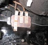
One item I only found out about later was that the depth of the battery box was shallow by about 1/2" so the screws that secure the overdrive relay body meant that the relay was 1/2" too high and I had trouble installing the Smiths heater. So out with the heater and I made a small extension plate so the relay body would be lower and that solved the problem.
One item I only found out about later was that the depth of the battery box was shallow by about 1/2" so the screws that secure the overdrive relay body meant that the relay was 1/2" too high and I had trouble installing the Smiths heater. So out with the heater and I made a small extension plate so the relay body would be lower and that solved the problem.
Attachments
OP
CJD
Yoda
Online
So it Monday and I'm eagerly waiting for the next episode!
Sorry...afraid that between work and weather I nothing done this week. Bummer. I'm doing better for next (this) week, though!
OP
CJD
Yoda
Online
John - I did exactly the same as you did when I restored my TR3A in 1987-1990. Everyone of your details.
One item I only found out about later was that the depth of the battery box was shallow by about 1/2" so the screws that secure the overdrive relay body meant that the relay was 1/2" too high and I had trouble installing the Smiths heater. So out with the heater and I made a small extension plate so the relay body would be lower and that solved the problem.
Uh Oh...that's one measurement I didn't even think about taking on the replacement box! Thanks for the tip, Don, I'll definitely double check the box depth before I go farther on it.
OP
CJD
Yoda
Online
Week 34
Yes...I did take 3 weeks off. I passed the 6 month point on solid bodywork and needed a break. But, I'm back into it.
This week the job was the front body mounts on the clip. The body mounts are spot welded to the inner wing, and the problem is that water corroded this joint from the inside out. The mounts are 16 gage metal, so they are still usable, but the 20 gage inner wings are holed and buckling. I will have to cut out the tattered part of the inner wings and patch with new metal.
Let's get started...
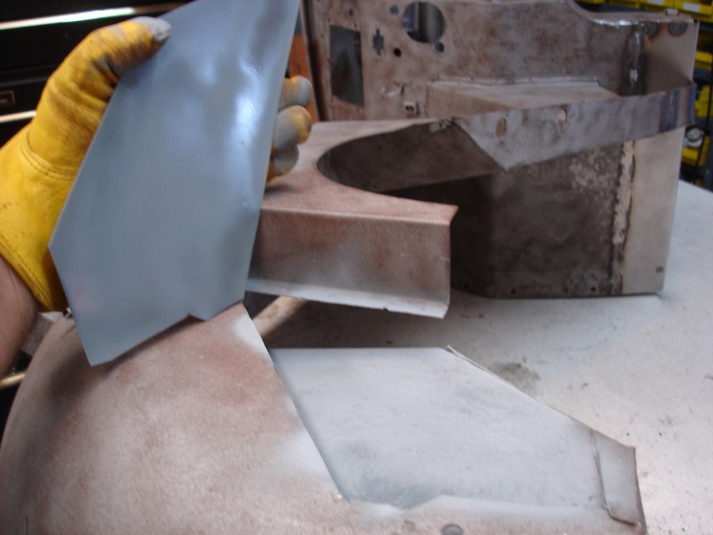
As always, get your patch all made before you do any serious metal removal. Here I have the new patch, and will scribe it's shape onto the inner wing, so I know what to remove.
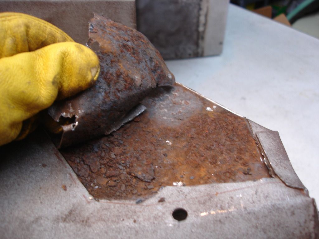
Once the patch is shaped, it's time to remove the bad metal. Here you get a good view of what was causing the metal to buckle.
Getting close...
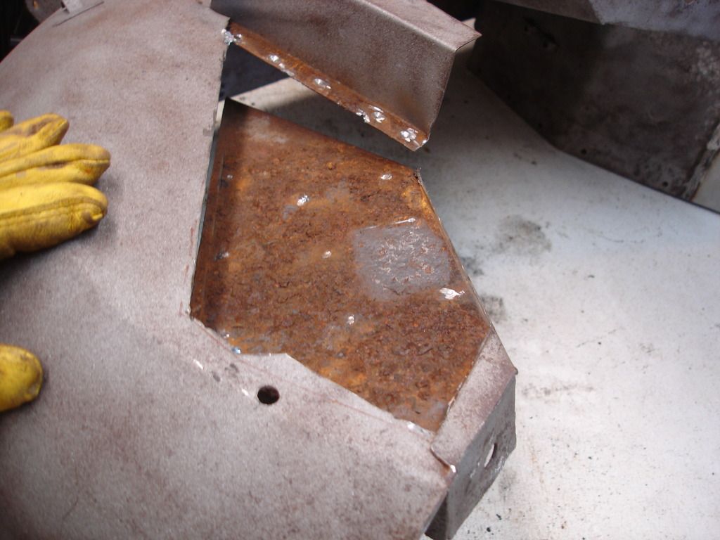
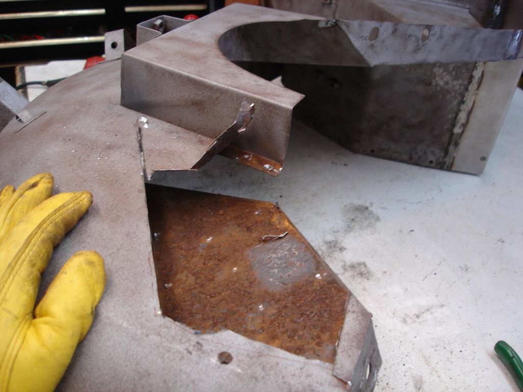
And there. All the bad metal is removed. The body mount is still rough, but it has enough metal left that I am not worried about strength.
Note...normally, at this point I would take the part outside and sand blast the rust off the mount. But, the part...being the entire front clip...being so large, I fudged and just wire brushed the rust. I was too lazy to carry the entire clip out back, but I wish I had. Later, when I start to weld onto this surface rust, and no matter how much I wire brushed it...it made a very difficult surface to penetrate with the weld. You will see what I mean as we progress.
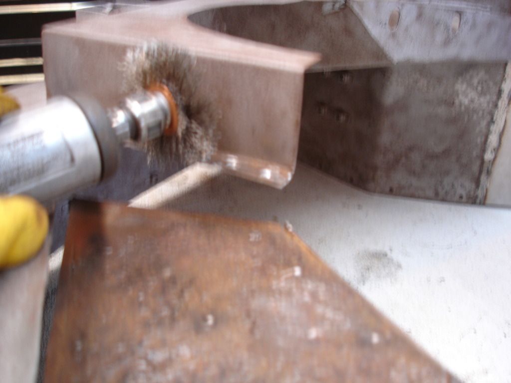
Here goes the wire brushing.
Unlike the factory, I primed the inside of the mount joint. Not that it matters, but if it took 60 years to rust through the first time...it ought to take much longer to rust through the next time!?!
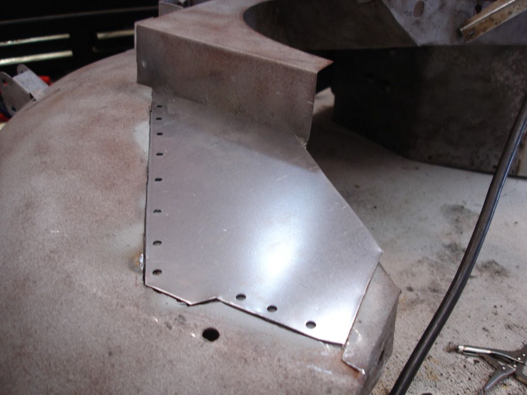
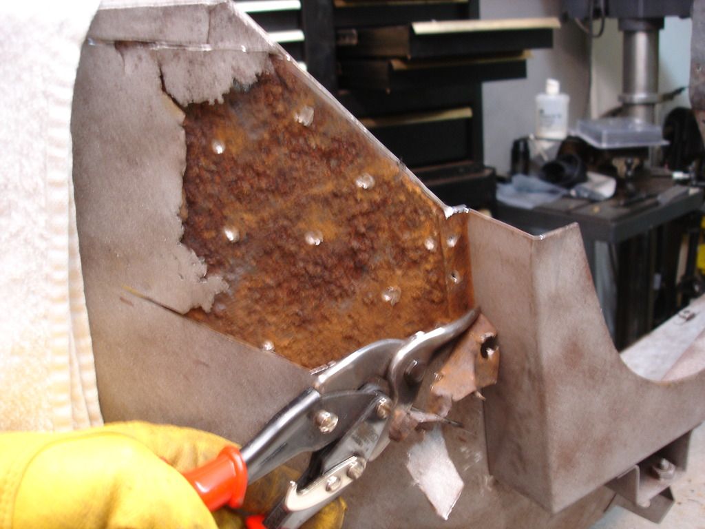
Noticed I punched holes to hole weld the patch onto the mount.
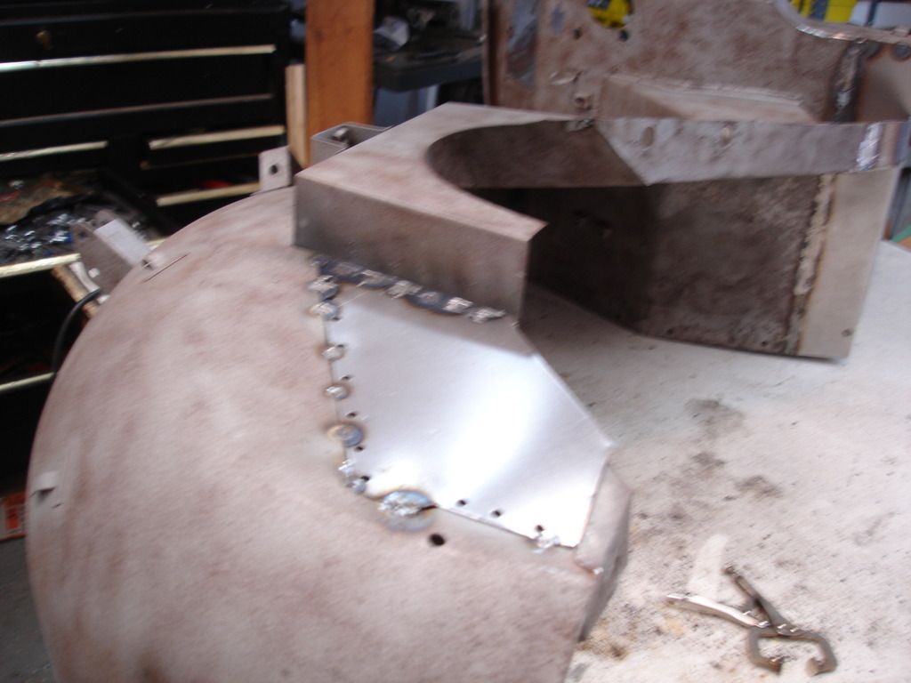
And here goes the hole welding.
Now, this is where things went south. The poor surface on the mount, combined with the primer (even though it is "weld through" on the label, made the hole welds completely ineffective. I would do a weld, and a few seconds later I would hear a "ping", as the two panels pulled back apart. I would then have to re-drill the holes and do it again...but, in the mean time, every hole spread the plates apart just a bit, so the whole patch slowly went to h#%* in a handbag. Through perseverance I managed to get it together, but next time I will sand blast the part, regardless of the effort it takes to do it.
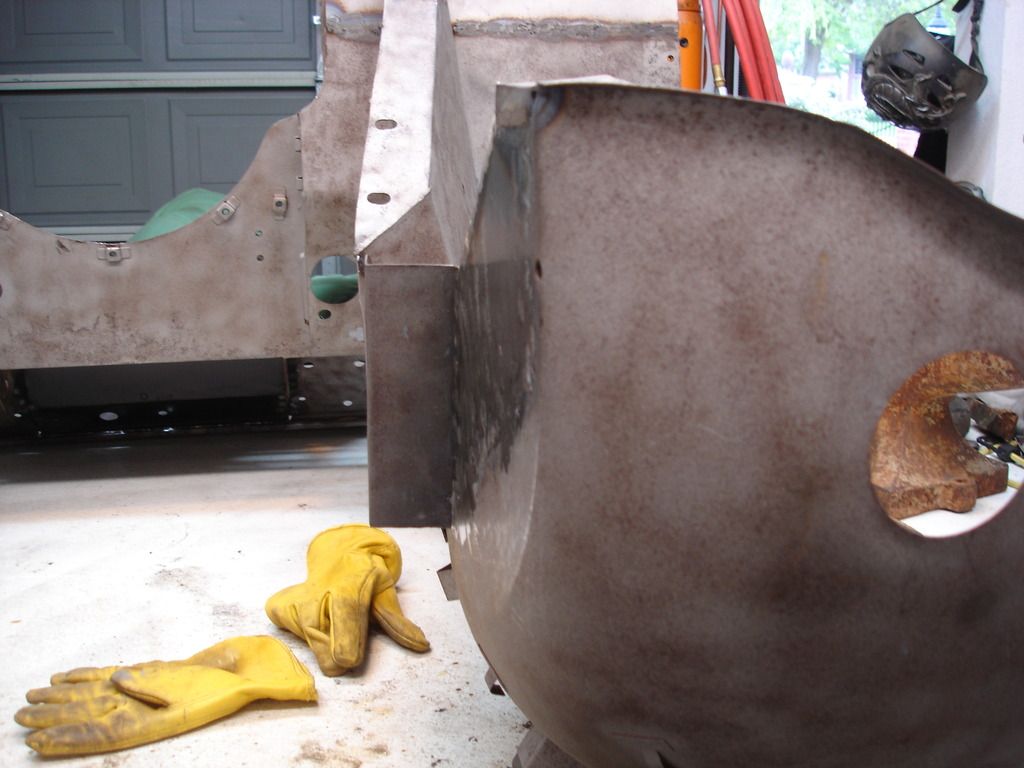
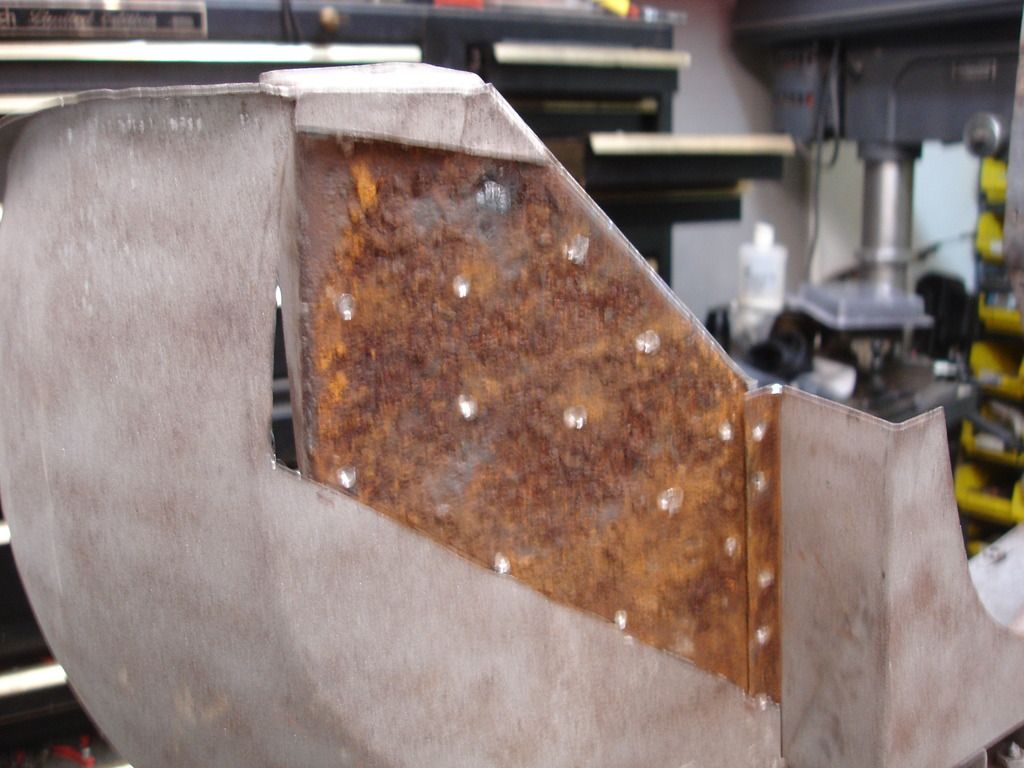
This angle shows that this particular area is flat. That compounds the work involved. You can always fudge a curve. There is no way to fudge flat! I was not happy with the patch, but it is close enough. WIth most of my body work it is close enough to finish with primer alone. This area will take a glaze to finish it off. Fortunately it is buried behind the apron so far that it will never show.
Yep, believe it or not, that was the better side! Time for the bad side.
The patch panel is fashioned, and then I started in with the cut-off disc.
Now just a matter of cutting and pealing.
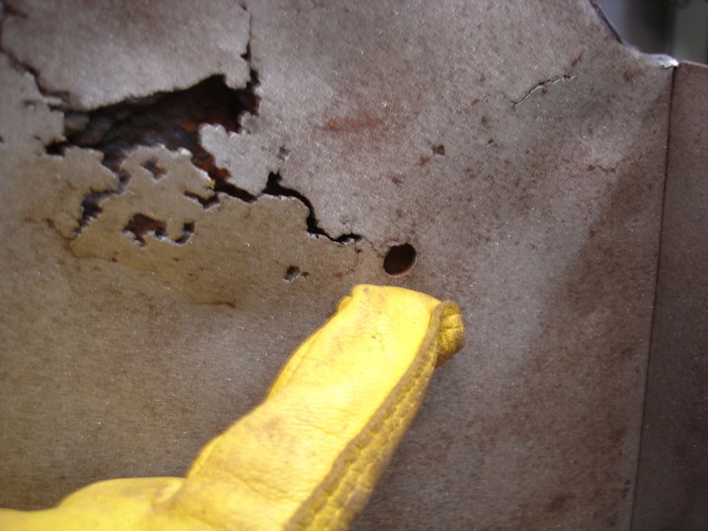
Here is the root of all this rust. For some unknown reason, the factory placed a hole in the wings, so water could enter and fester between the mount plate and wing. Small hole, 60 years, and the result is ugly!
As I worked down, you can see the random spot welds that had to be drilled and ripped apart. Uhg!
And here is the area ready to brush and patch.
Note...last time I put the welding holes in the good (new) panel, and attempted to weld into the old (rusty) mount panel. I CAN still learn...sometimes! This time I reversed the operation. I drilled the holes into the rusty panel and welded through into the new panel. This worked much better.
I brushed, ground, and finally drilled the mount panel in preparation for the patch.
Once again...don't forget to prime!
Along the suspension tower I did still drill the weld holes in the patch.
Panel on.
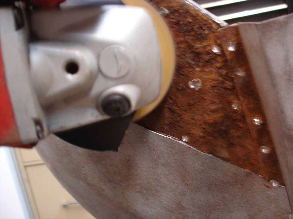
And following all the grinding and hammering...
So...another week down. This week I only have the rear body mounts to replace...the ones that mount to the spring tower diagonals. And, then, comes the elephant in the shop. I have to switch from bodyman/welder to millwright. I have to fab the new wood insert for the dash. Fun, Fun!?!
Until next week...
Yes...I did take 3 weeks off. I passed the 6 month point on solid bodywork and needed a break. But, I'm back into it.

This week the job was the front body mounts on the clip. The body mounts are spot welded to the inner wing, and the problem is that water corroded this joint from the inside out. The mounts are 16 gage metal, so they are still usable, but the 20 gage inner wings are holed and buckling. I will have to cut out the tattered part of the inner wings and patch with new metal.
Let's get started...

As always, get your patch all made before you do any serious metal removal. Here I have the new patch, and will scribe it's shape onto the inner wing, so I know what to remove.


Once the patch is shaped, it's time to remove the bad metal. Here you get a good view of what was causing the metal to buckle.

Getting close...

And there. All the bad metal is removed. The body mount is still rough, but it has enough metal left that I am not worried about strength.
Note...normally, at this point I would take the part outside and sand blast the rust off the mount. But, the part...being the entire front clip...being so large, I fudged and just wire brushed the rust. I was too lazy to carry the entire clip out back, but I wish I had. Later, when I start to weld onto this surface rust, and no matter how much I wire brushed it...it made a very difficult surface to penetrate with the weld. You will see what I mean as we progress.

Here goes the wire brushing.

Unlike the factory, I primed the inside of the mount joint. Not that it matters, but if it took 60 years to rust through the first time...it ought to take much longer to rust through the next time!?!

Noticed I punched holes to hole weld the patch onto the mount.

And here goes the hole welding.
Now, this is where things went south. The poor surface on the mount, combined with the primer (even though it is "weld through" on the label, made the hole welds completely ineffective. I would do a weld, and a few seconds later I would hear a "ping", as the two panels pulled back apart. I would then have to re-drill the holes and do it again...but, in the mean time, every hole spread the plates apart just a bit, so the whole patch slowly went to h#%* in a handbag. Through perseverance I managed to get it together, but next time I will sand blast the part, regardless of the effort it takes to do it.


This angle shows that this particular area is flat. That compounds the work involved. You can always fudge a curve. There is no way to fudge flat! I was not happy with the patch, but it is close enough. WIth most of my body work it is close enough to finish with primer alone. This area will take a glaze to finish it off. Fortunately it is buried behind the apron so far that it will never show.

Yep, believe it or not, that was the better side! Time for the bad side.

The patch panel is fashioned, and then I started in with the cut-off disc.

Now just a matter of cutting and pealing.

Here is the root of all this rust. For some unknown reason, the factory placed a hole in the wings, so water could enter and fester between the mount plate and wing. Small hole, 60 years, and the result is ugly!

As I worked down, you can see the random spot welds that had to be drilled and ripped apart. Uhg!

And here is the area ready to brush and patch.
Note...last time I put the welding holes in the good (new) panel, and attempted to weld into the old (rusty) mount panel. I CAN still learn...sometimes! This time I reversed the operation. I drilled the holes into the rusty panel and welded through into the new panel. This worked much better.


I brushed, ground, and finally drilled the mount panel in preparation for the patch.

Once again...don't forget to prime!

Along the suspension tower I did still drill the weld holes in the patch.

Panel on.

And following all the grinding and hammering...
So...another week down. This week I only have the rear body mounts to replace...the ones that mount to the spring tower diagonals. And, then, comes the elephant in the shop. I have to switch from bodyman/welder to millwright. I have to fab the new wood insert for the dash. Fun, Fun!?!
Until next week...
M_Pied_Lourd
Darth Vader
Offline
Good Job. That is a tricky little area. I wasn't able to save my bracket as it was very thing and rusty. I was fortunate that Don E had some left over brackets from his restoration, so I ended up cutting out a replacing with new metal and then spot welded the body mount bracket on the rear.
Here is what mine looked like on the drivers side.

Cheers
Tush
Here is what mine looked like on the drivers side.
Cheers
Tush


Hello John.
I am following your work with great interest as I have little or no body work experience. Metal work ok but no body work. It is like an on line body work class.
I noticed some time back when you were working on the front wings (Fenders) you made your own repair piece. Was that because the repair pieces are too small or do not fit well?
Also on the inner wing repair you have just completed was the dogleg in the patch to help with alignment of the patch.
I will have to start a thread of my work redoing the Previous Owners attempts at repair. I know I can do better. Fiberglass is not on the menu.
David
OP
CJD
Yoda
Online
Week 35
"Yo Bubba". I finished the front clip welding this week. That's a plus. It needs sand blasting now, and the Texas heat is moving in. That's a minus.
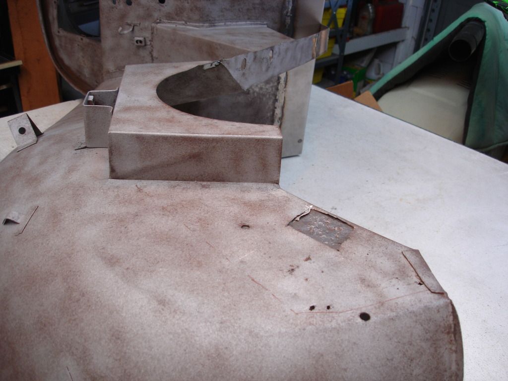
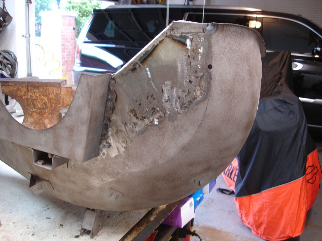
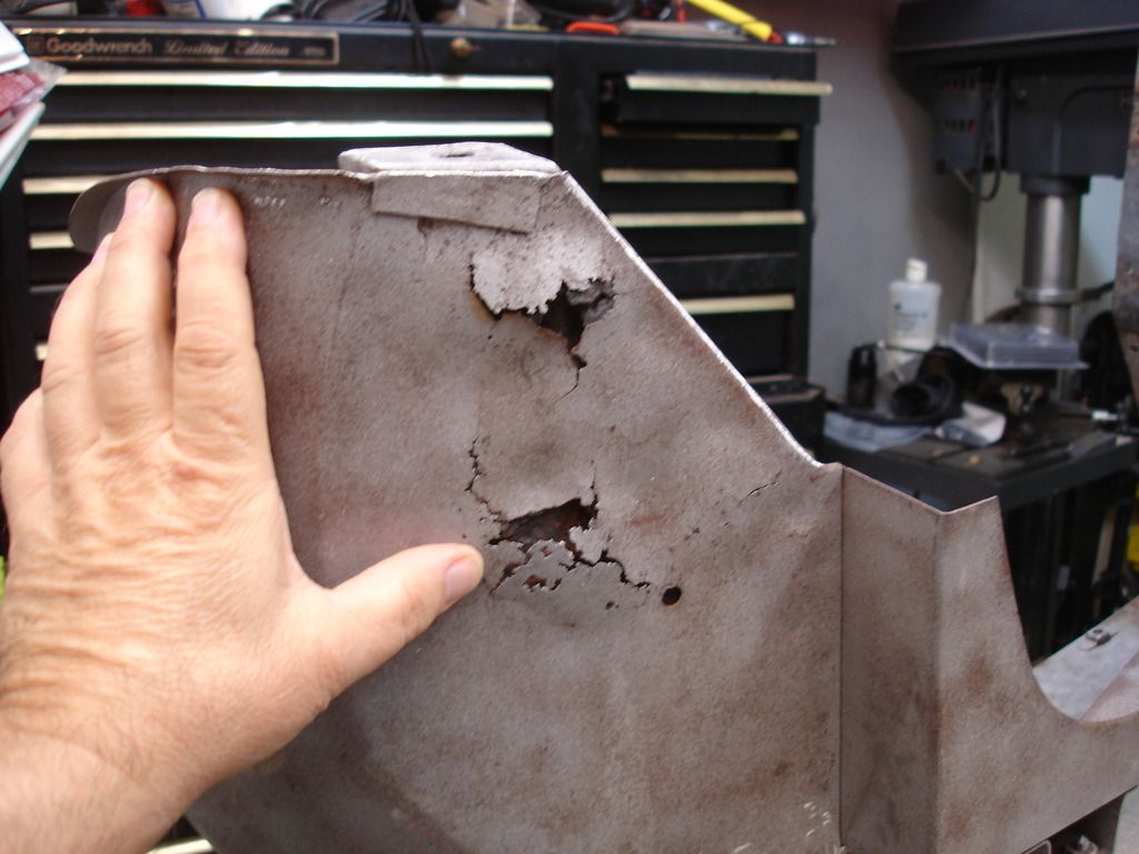
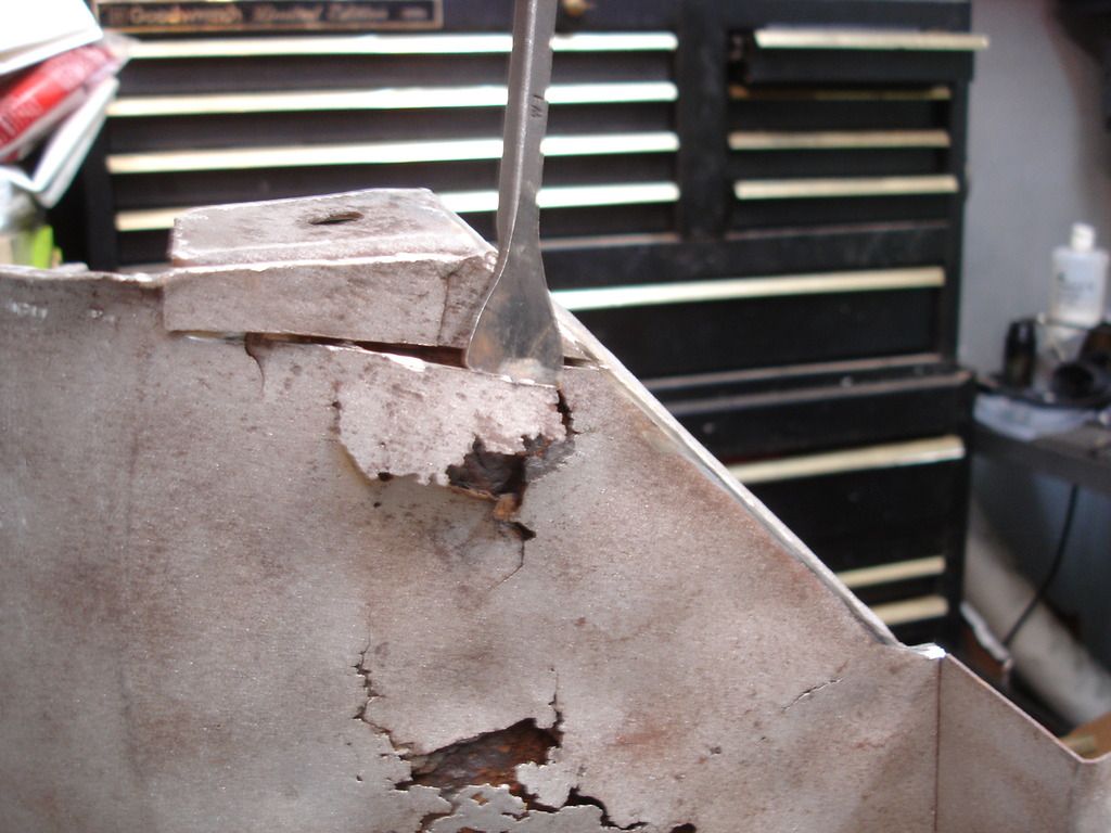
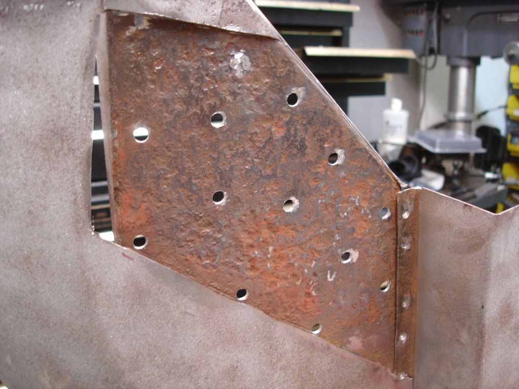
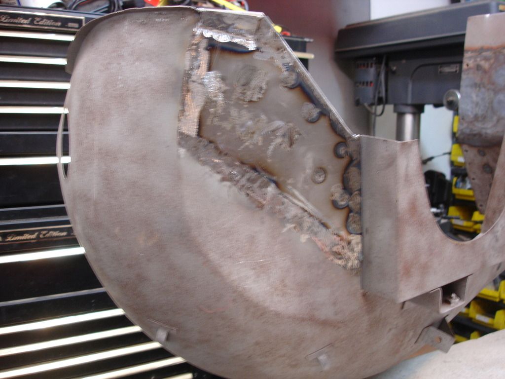
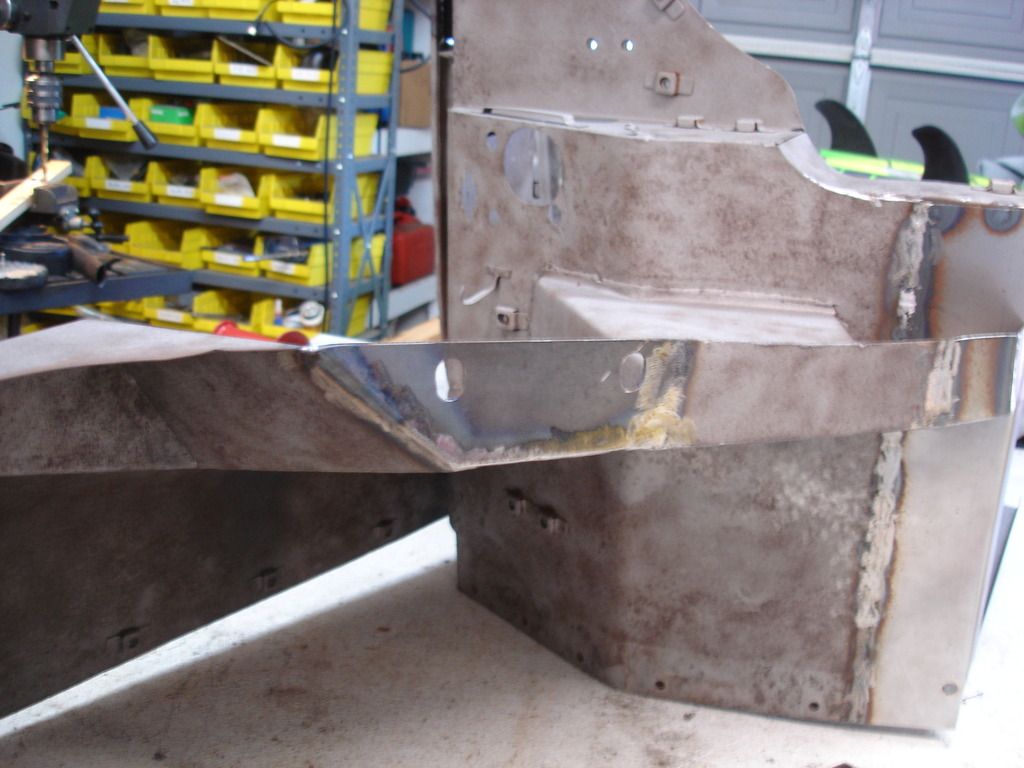
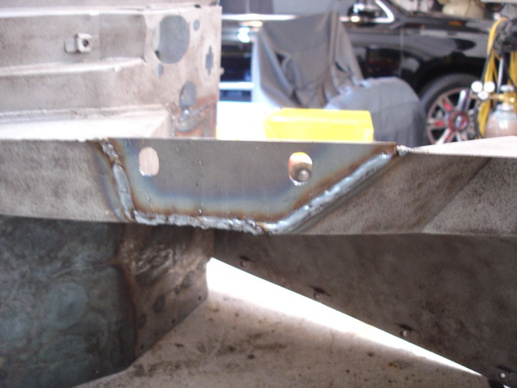
SO, the last of the welding was the next set of body mounts...the ones that bolt on to the suspension 45 degree struts on each side.
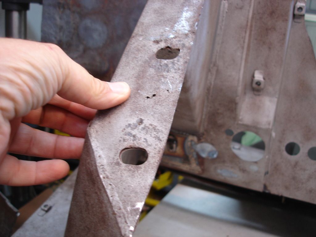
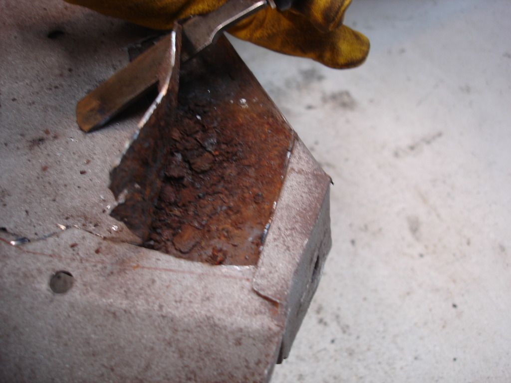
They were littered with little pin holes. This area is actually made when several front body parts are folded together, making a sandwich of 3 layers of 20 gage steel. I looked and studied, studied and looked, drank beer and studied, drank beer and looked.
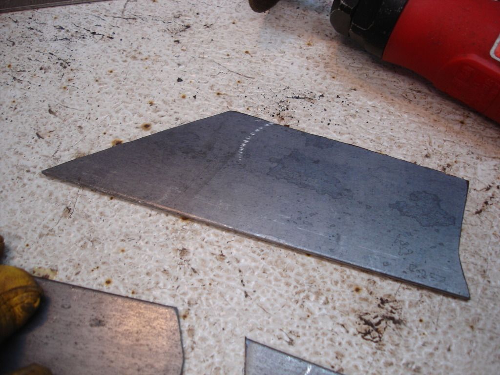
In the end, I decided that was much too much work...folding 3 layers over...to make a part that would be prone to rusting from the inside out AND doesn't show once it is installed. I decided to swap the 3 layers of 20 gage for a single layer of 14 gage. Much easier!
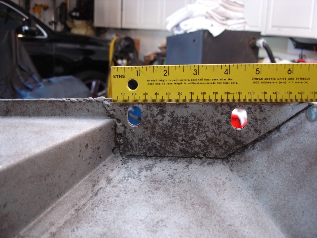
Of course, the mandatory measurements were taken.
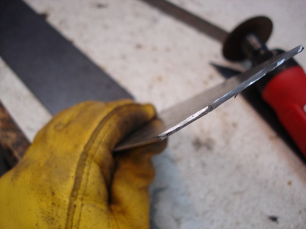
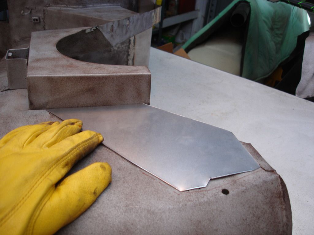
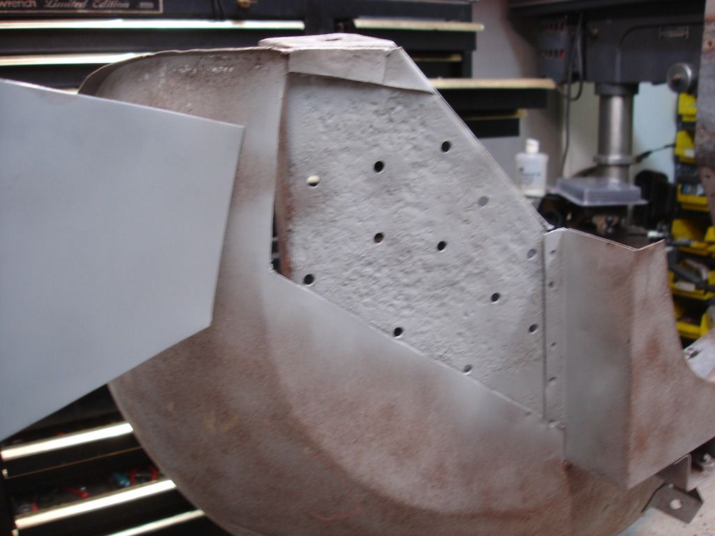
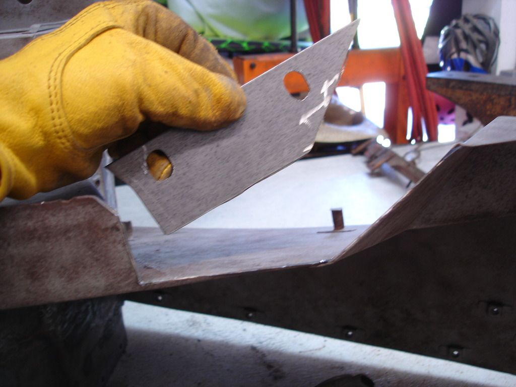
And the 14 gage patches were cut out before removing the old mounting pads. Here you can see how much thicker this metal is. I guarantee it won't rust out in my life time!
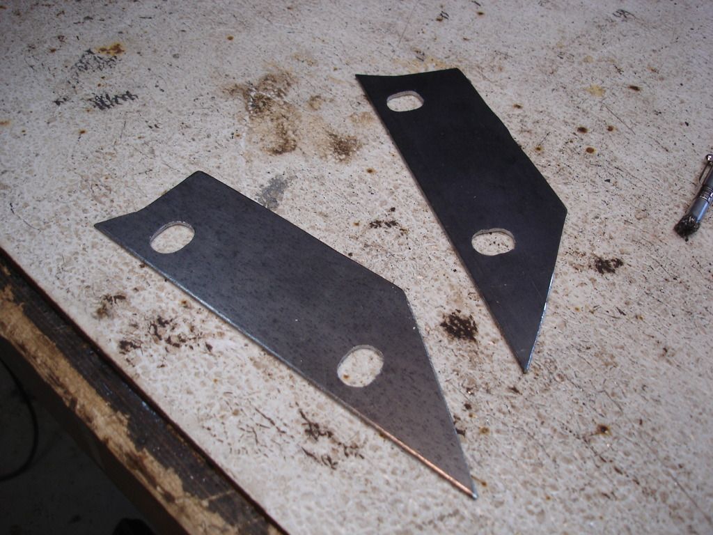
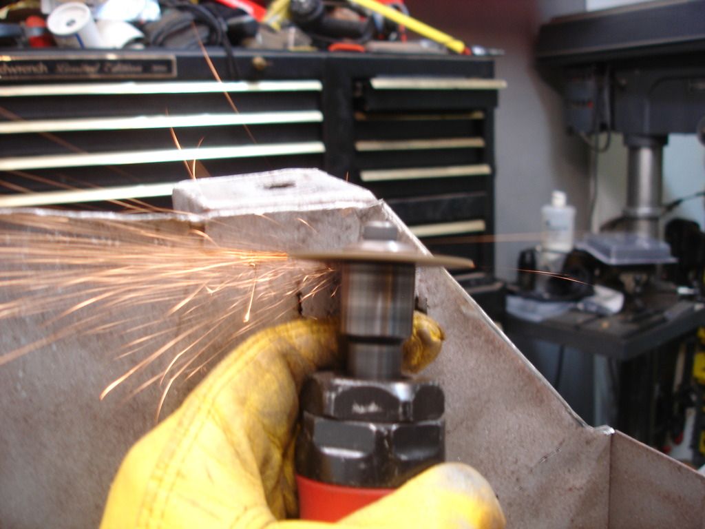
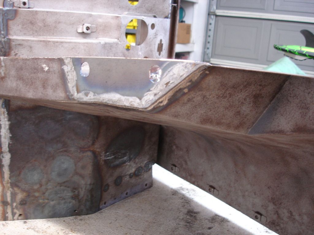
A little time and more Beer...and the patches are ready to go in. The 14 gage is much too thick to use shears.,..even my fancy new pneumatic shears, so these were cut using a cut-off wheel.
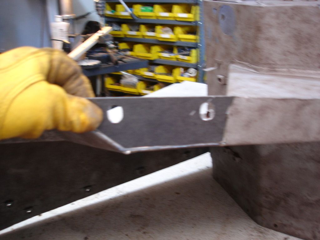
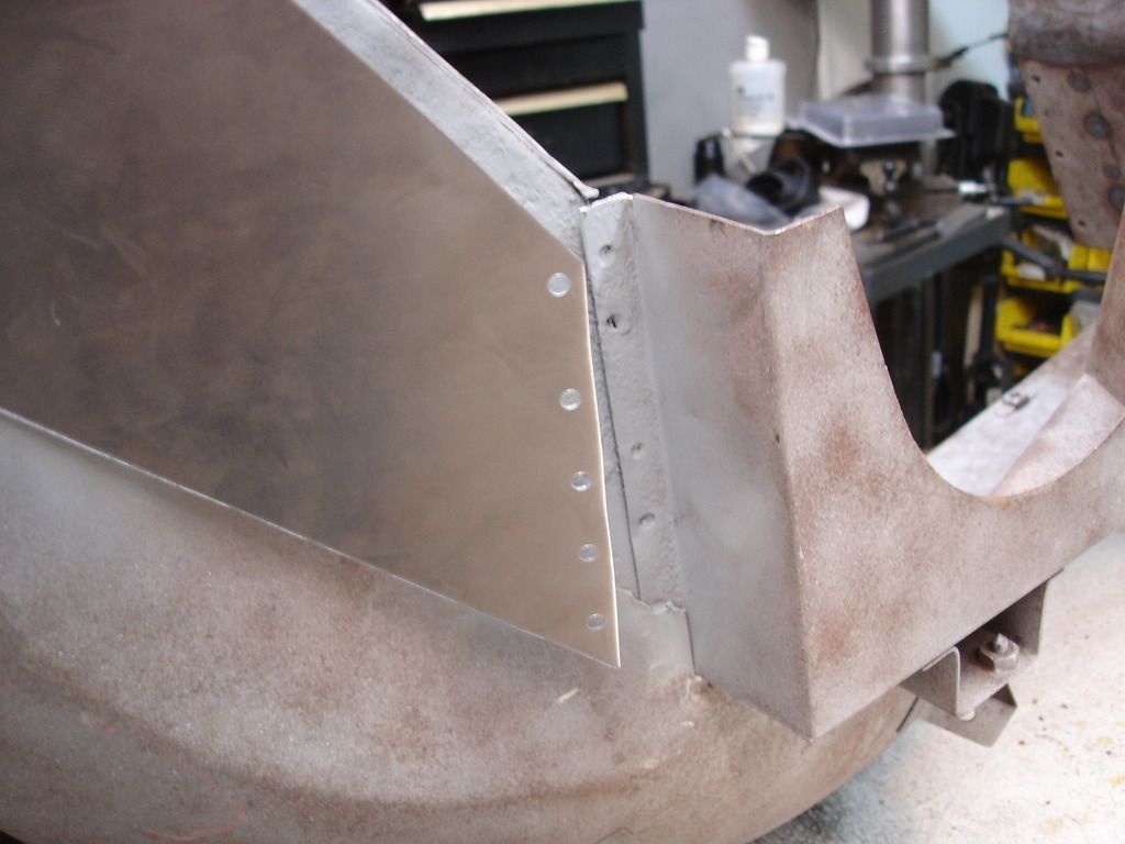
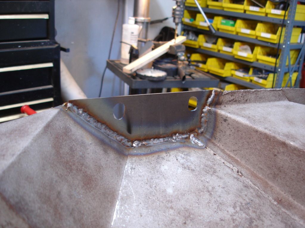
After a little grinding to get a perfect fit, the first patch gets tacked in.

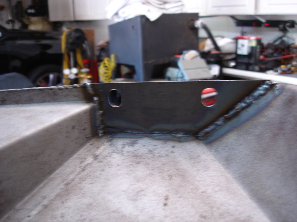
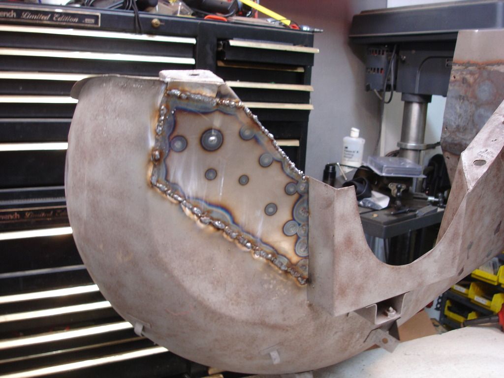
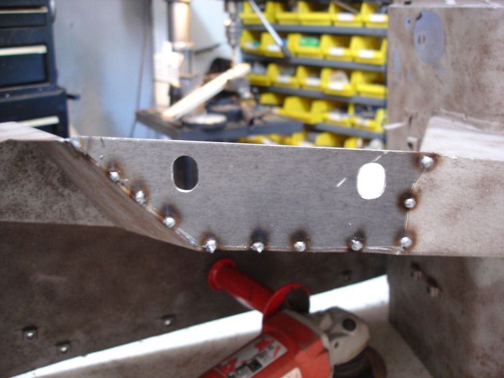
Welded on both sides.
And ground smooth to hide the work. And that ends side one.
Side 2 is more of the same...
And, just like that, the 2-1/2 months of banging and welding on the front clip is over...wheeeew!
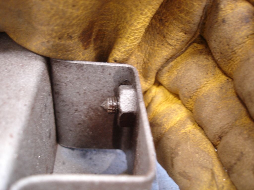
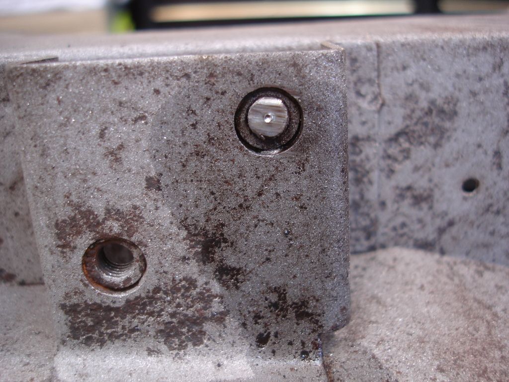
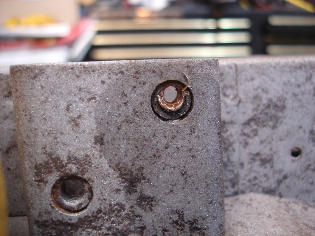
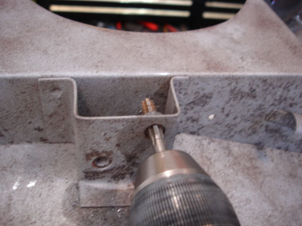
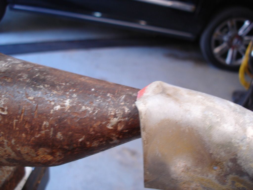
The last metal work that remains is this one last broken off bolt. Since it is open in the back, I first tried to PB blast it and unscrew from the back side. I could not quite get a grip with the vise grips, so I had to resort to plan "B"...the drill...
To get a centered start on the first hole, it's important to grind a nice flat on the broken bolt to give a good starting point.

Then center punch a divot for the drill bit to stay centered.
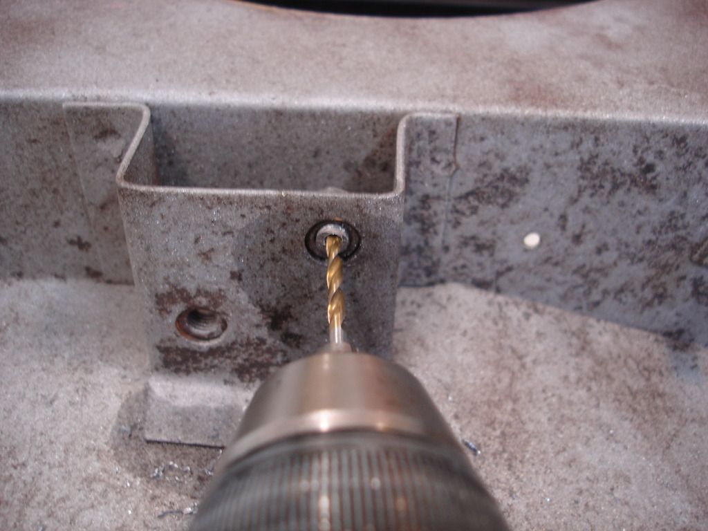
Always start with a very small bit, and gradually work up in size. This makes sure you will not damage the threads, especially if the hole is off center...which it invariably is by some amount.
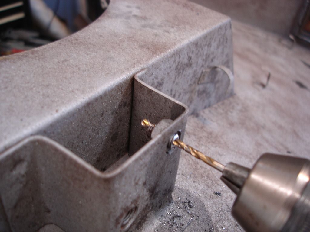
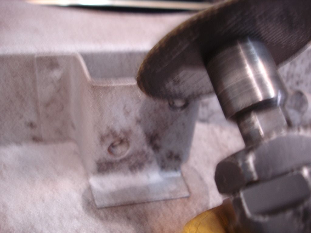
Little bigger bit...
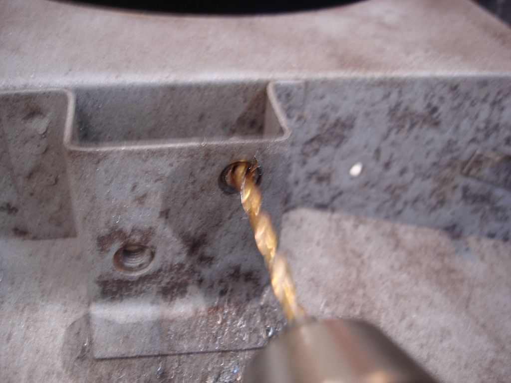
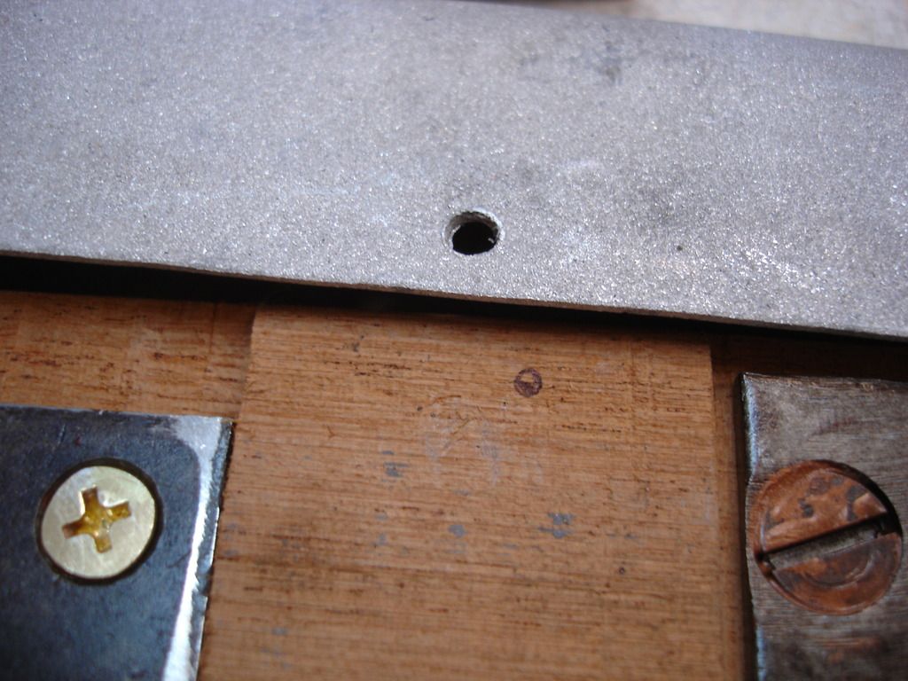
And the biggest bit that would go without touching the female threads. Notice that while the first bit looked perfectly centered...this last one is not. For whatever reason, it is common to get a bit of drift as you size up. No biggy, though. Just stop before damaging the threads.
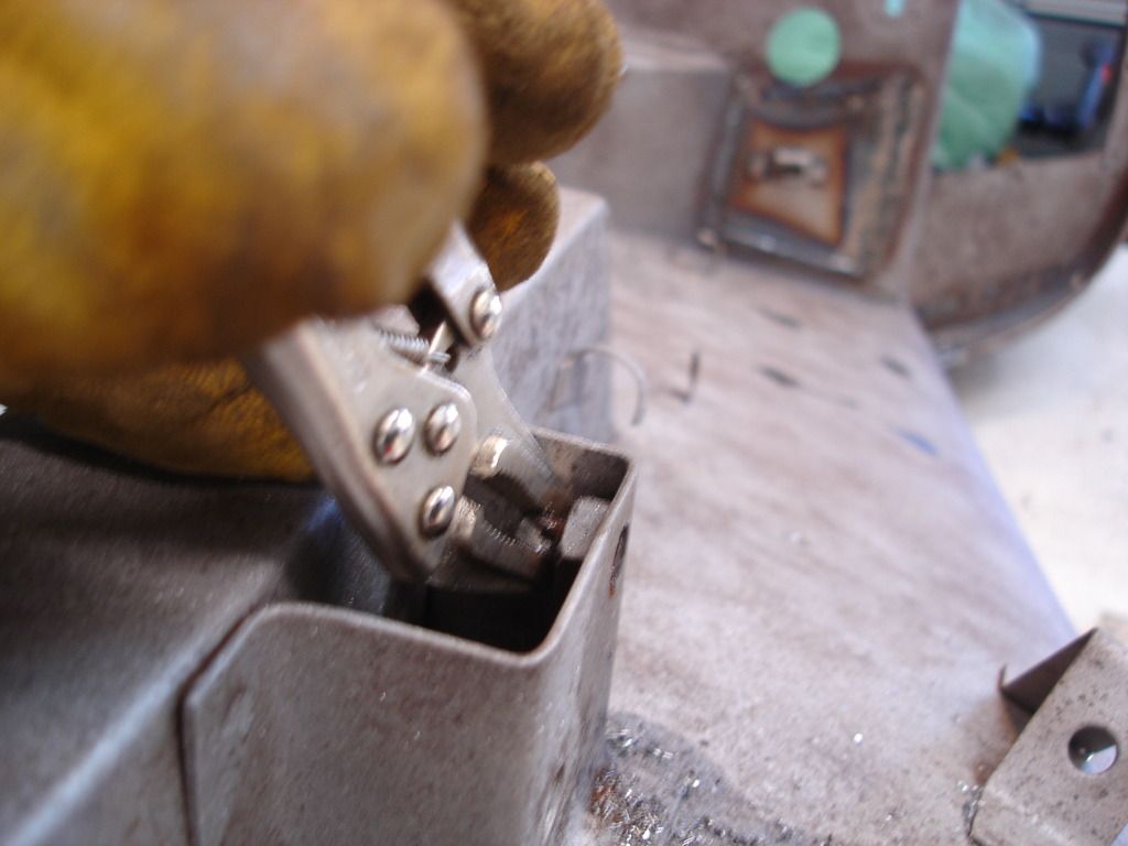
Normally, I would switch to a 1/4-28 tap at this point and spin the remaining bolt metal right out. In this case I was fortunate that I can reach the bolt from the back...so I just unscrewed what was left from the back side.
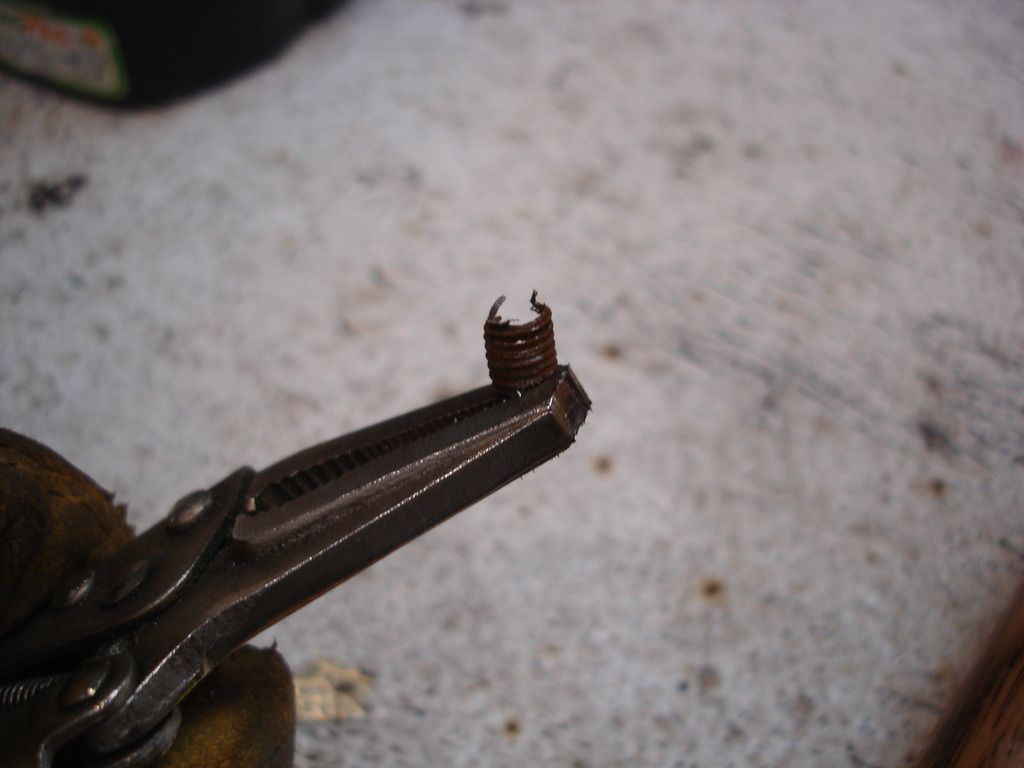
Like so...
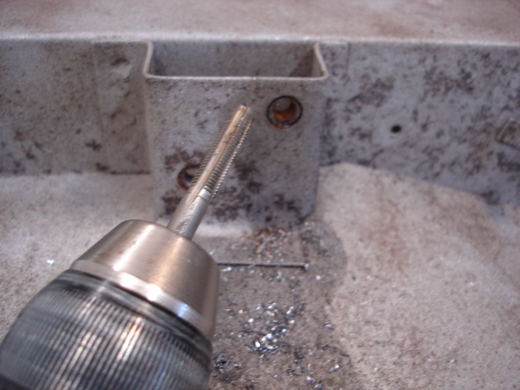
Add a little oil to a tap and clean out the female threads. Done! While the taps are out...good time to clean up ALL of the female threads on the front clip. A few minutes now with a tap will save hours of cussing later...and help the beer tab...a bit!
So, by mid week the metal work is done. Yippee!
"Yo Bubba". I finished the front clip welding this week. That's a plus. It needs sand blasting now, and the Texas heat is moving in. That's a minus.
SO, the last of the welding was the next set of body mounts...the ones that bolt on to the suspension 45 degree struts on each side.

They were littered with little pin holes. This area is actually made when several front body parts are folded together, making a sandwich of 3 layers of 20 gage steel. I looked and studied, studied and looked, drank beer and studied, drank beer and looked.
In the end, I decided that was much too much work...folding 3 layers over...to make a part that would be prone to rusting from the inside out AND doesn't show once it is installed. I decided to swap the 3 layers of 20 gage for a single layer of 14 gage. Much easier!

Of course, the mandatory measurements were taken.

And the 14 gage patches were cut out before removing the old mounting pads. Here you can see how much thicker this metal is. I guarantee it won't rust out in my life time!


A little time and more Beer...and the patches are ready to go in. The 14 gage is much too thick to use shears.,..even my fancy new pneumatic shears, so these were cut using a cut-off wheel.


After a little grinding to get a perfect fit, the first patch gets tacked in.


Welded on both sides.

And ground smooth to hide the work. And that ends side one.
Side 2 is more of the same...


And, just like that, the 2-1/2 months of banging and welding on the front clip is over...wheeeew!

The last metal work that remains is this one last broken off bolt. Since it is open in the back, I first tried to PB blast it and unscrew from the back side. I could not quite get a grip with the vise grips, so I had to resort to plan "B"...the drill...

To get a centered start on the first hole, it's important to grind a nice flat on the broken bolt to give a good starting point.

Then center punch a divot for the drill bit to stay centered.


Always start with a very small bit, and gradually work up in size. This makes sure you will not damage the threads, especially if the hole is off center...which it invariably is by some amount.

Little bigger bit...


And the biggest bit that would go without touching the female threads. Notice that while the first bit looked perfectly centered...this last one is not. For whatever reason, it is common to get a bit of drift as you size up. No biggy, though. Just stop before damaging the threads.

Normally, I would switch to a 1/4-28 tap at this point and spin the remaining bolt metal right out. In this case I was fortunate that I can reach the bolt from the back...so I just unscrewed what was left from the back side.

Like so...


Add a little oil to a tap and clean out the female threads. Done! While the taps are out...good time to clean up ALL of the female threads on the front clip. A few minutes now with a tap will save hours of cussing later...and help the beer tab...a bit!

So, by mid week the metal work is done. Yippee!
OP
CJD
Yoda
Online

Yes...what you've all been waiting for...what the H3JJ am I going to do with the wood dash insert. I did spend several hours on the internet, only to learn that this is no longer available, from, basically, anywhere anymore.
Bummer!
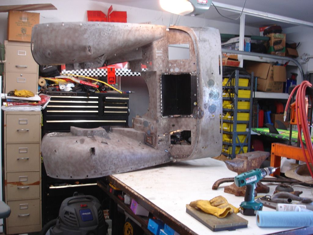
But, no worries. I had to switch the shop over from metal mode to wood mode...rearranging the cars and tools a bit. But soon I was ready to dive in.

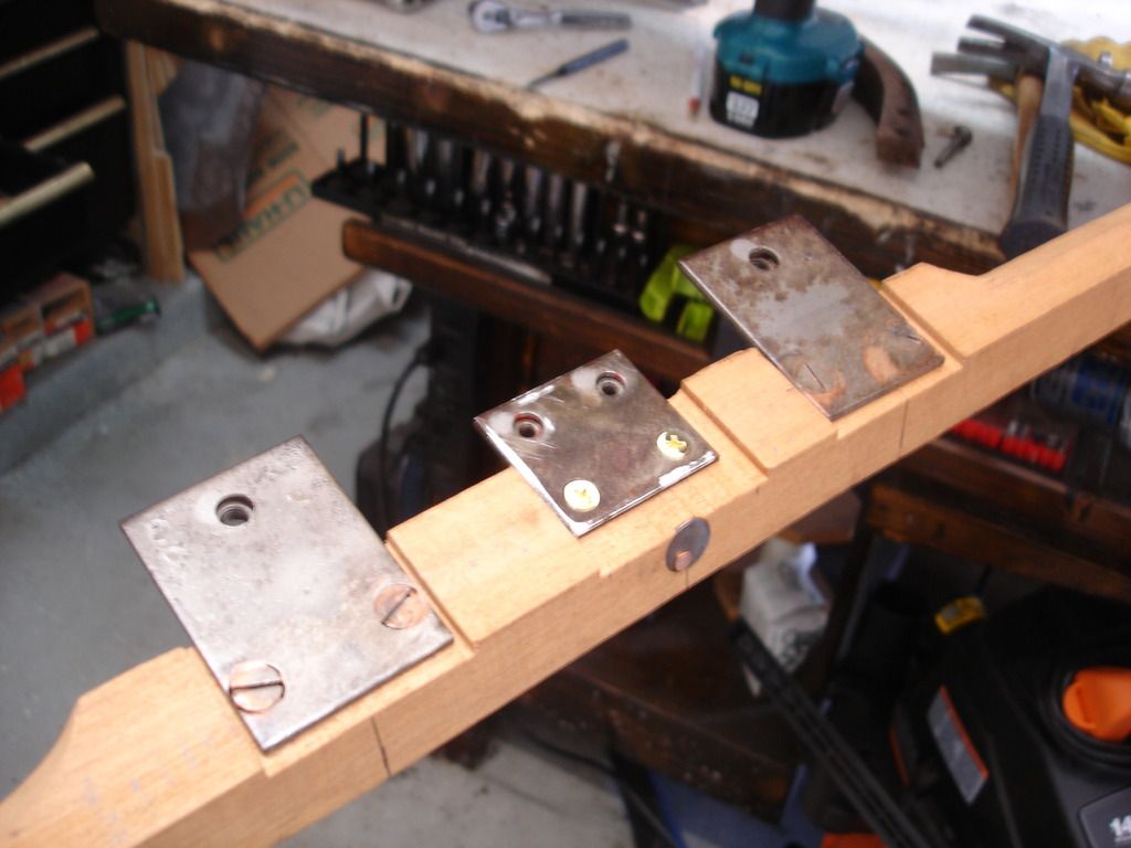
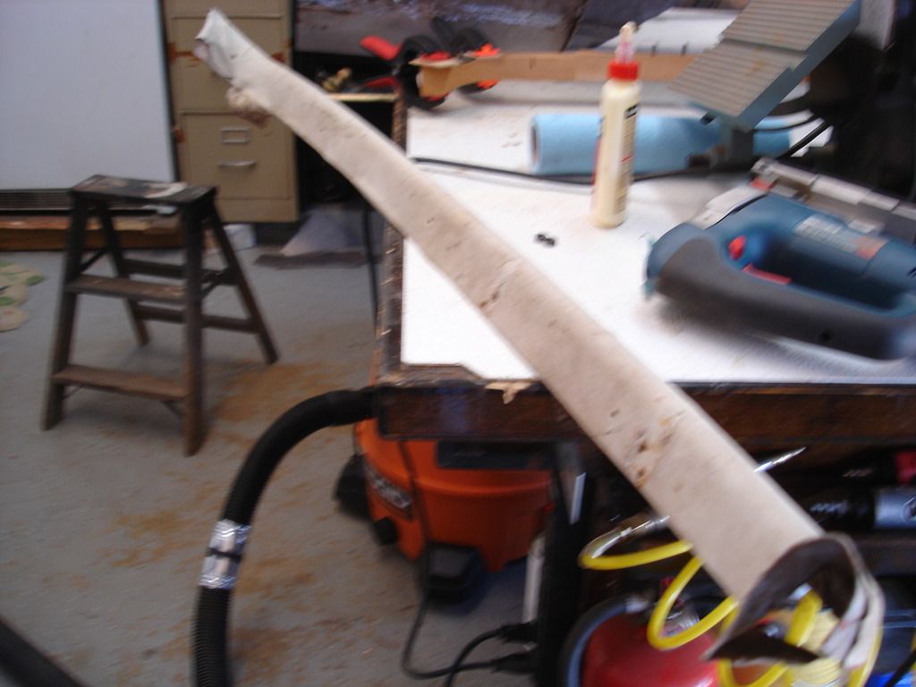
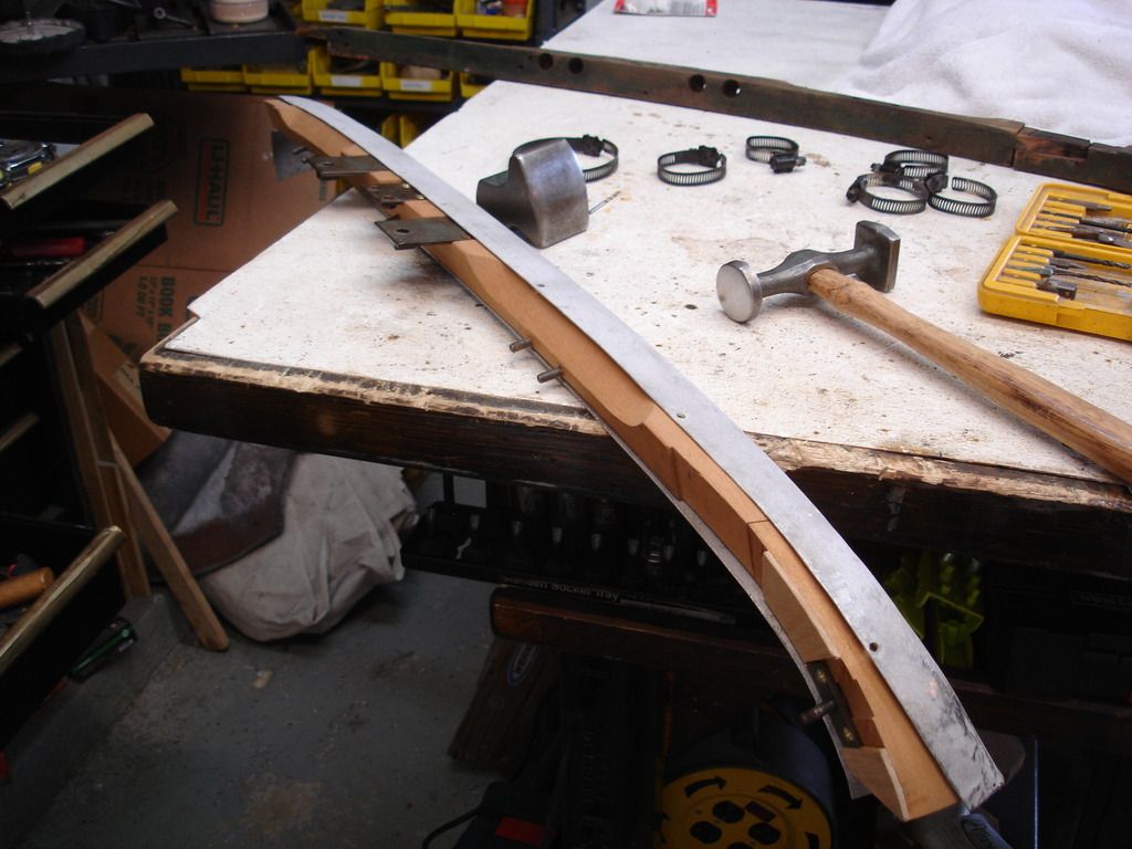
The insert is composed of 3 parts. The long center, milled on the ends so it splices into the curved corner pieces...also milled.


Along the way there are a myriad of these type bolts, which hold the instrument panel and demister vents in place...


These plates and associated mill work which hold the mirror and racing windscreens in place...

And even more mill work and fancy studs to hold the instrument panel on the ends.
I am beginning to feel more like a boat builder than a car restorer.

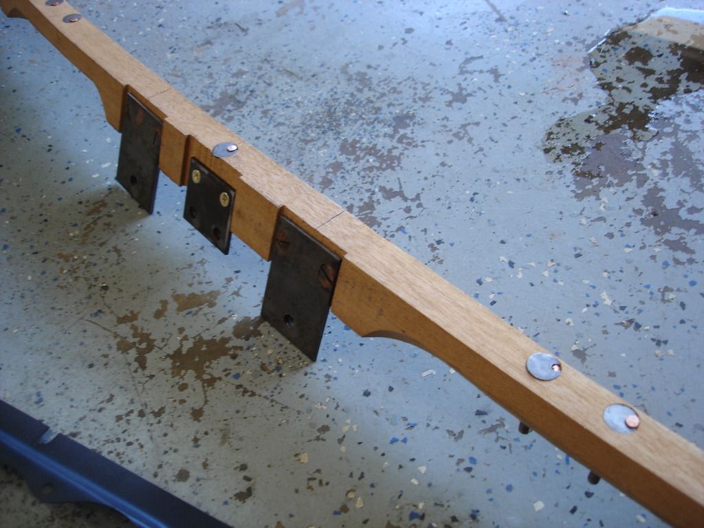
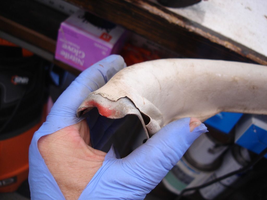
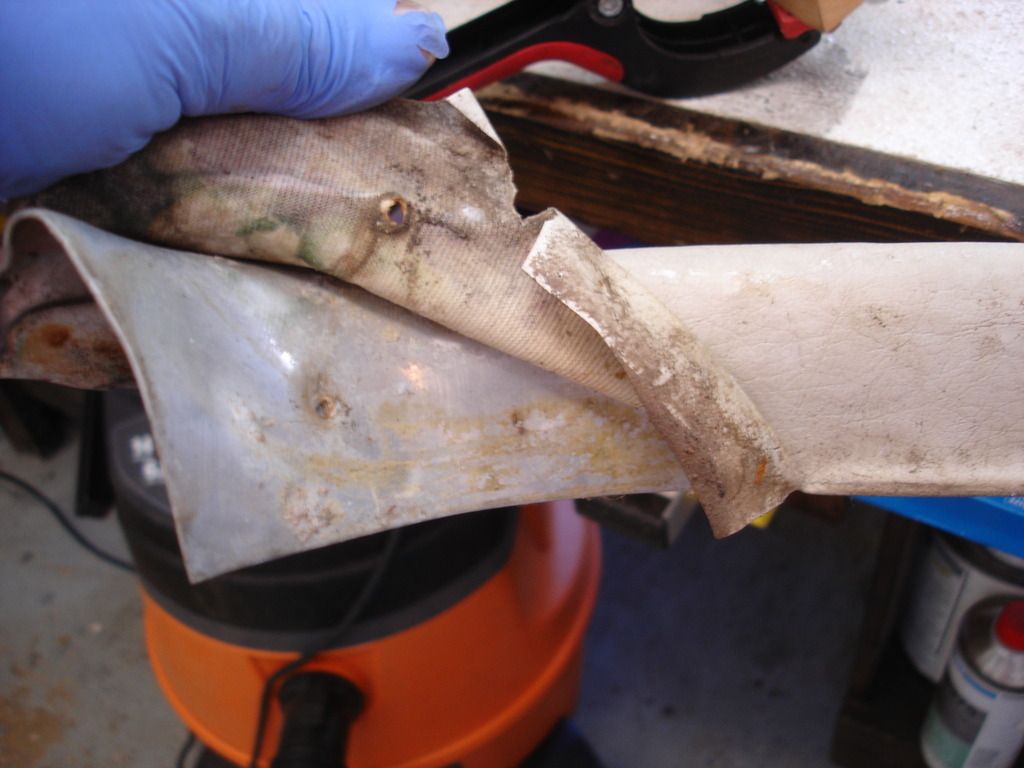
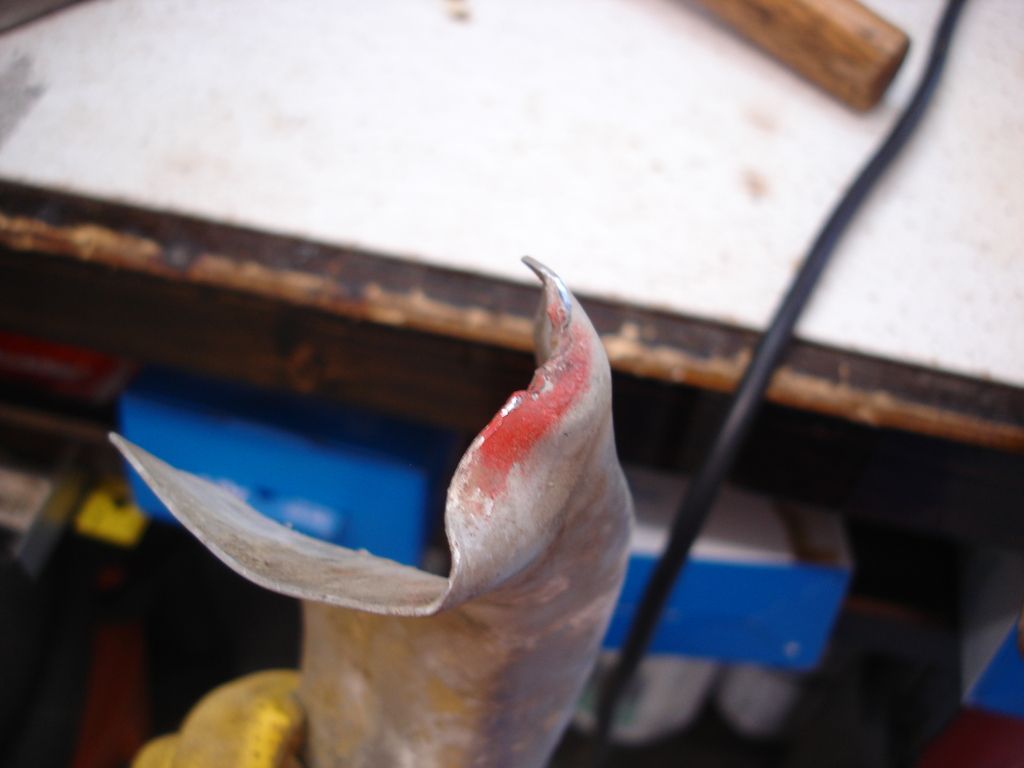
For strength, the end curved pieces run the wood grain at about a 45 degree angle. The old wood still split where it splices into the center insert.


First, all the hardware has to come out.


Racing screen brackets.

Mirror bracket.

Instrument panel brackets. (note for later that these have bent studs...remind Wife to purchase more beer!)

And the wood splice joints.
OP
CJD
Yoda
Online


As always, the measurements come first. (Don't ask how long it took me to remember this important step BEFORE destroying the original parts!?!)

A trip to the storage shed brought another section of 20 year seasoned African Mahogany. I did mention I'm feeling like a boat builder, right? I even bought this wood back when I used to build boats for a hobby!

First the center section. The measurements showed that 2 sides are actually parallel to each other. The other 2 sides have no common angles. In fact, 2 of the sides have no steady angles at all, but are continuously changing along their length. Yep...need to review the old boat building skills, including scarfing joints and working with scandlings and such.

I don't have room in the shop (read garage) to fit both the router table and table saw at once. So, this is a Dado blade in the table saw to end mill the joints at the ends. I will switch to the router when I am totally done with the saw.

Here is the slow, tedious, work shaping the insert to match the original. Slow work. No Beer here...bummer!

These are the reliefs that had to be shaped to make room for the demister vents. I can see why they switched to metal dashes by the TR3!! There is no end to the surprises this simple insert has in store!


Once again...Dado blade makes the mill work for the brackets.

At this point it is time to move to the end pieces. Time to get rid of the table saw. Because of the continuous curves, these will be cut with a sabre saw. I would use a band saw...if I had one...

Form the looks of these, a PO may have used this car as a boat. I may not be that far off??

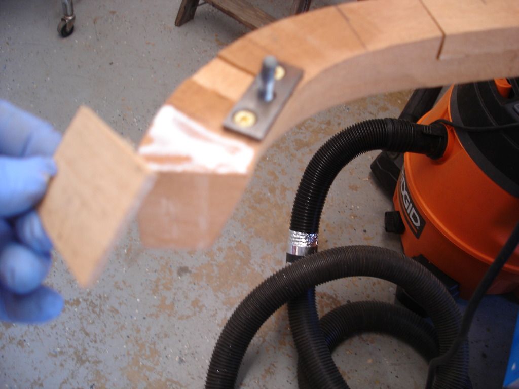
Tracing the shapes proved tricky. The sides have a continually changing curve, making it hard to find a true vertical while tracing. So I frequently had to use a square to make sure I was tracing the largest edge.

Sabre saw away! The tricky part here is making sure the blade is kept absolutely vertical. A band saw would make that task easier. (can you tell I really want a band saw yet?)

Rough blocks. Back to the sander...


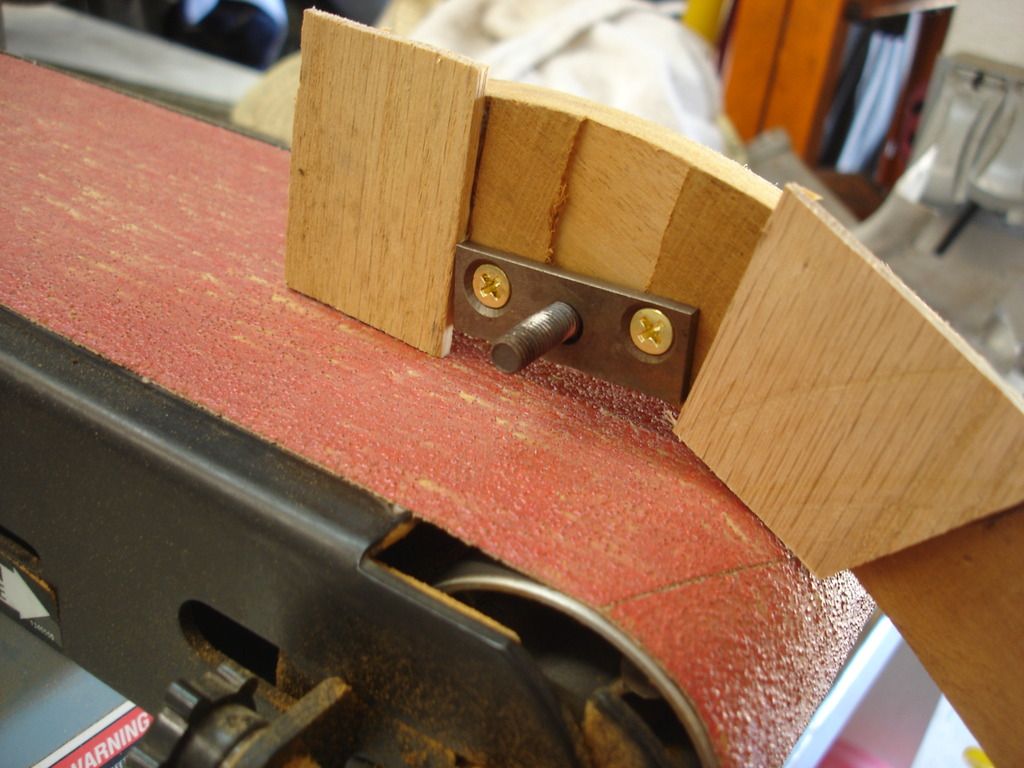
Above is a view of the corner shaping progress. Very tedious. These pieces only have a single flat face. The other 3 faces have continuously changing curves. Working slowly and being careful not to remove too much wood at once, they gradually came into shape.

Now the router table came out. It does a much neater job of the mill work slots.


And the center insert can finally meet the end inserts.

That was just the first block. Uhhgg!

Once they are both roughed out, it is time to make the 3 into 1. The original screws were slot head, of course. Slot head have to be special ordered now days. Since these are hidden and may never be out of the dash ever again...I may fudge and leave the phillips screws in. TBD...

The first trial fit. There is a catch 22 here. The insert will not fit if in 1 piece. If fit in 2 pieces, then the lip on the metal scuttle covers the screws that splice the wood parts together. This will take some thought to figure out. Anyone out there good with Rubik's cubes?

It was at this point that I realized that all of those myriad bolts could only be re-installed by matching their locations to the instrument panel. Another trip to the storage shed to get the panel. This pic gives an idea of how it all goes together.

Each bolt, nut, bracket, screw...envolves it's own succession of little milling operations. Above I am using a forstner bit to cut the relief for the center instrument mounting bolt.

Then comes the drilling operation for the bolt shaft.

Followed by the countersinking operation for the bolt head.

To get this shaped hole, for this specialized bolt.

Only the Brits would think to "tack " the bolt in place! Why didn't we think of that..? Oh, yeah, because this is a CAR...not a BOAT!!!


And...one of the 7 mounting bolts is installed. Only 6 more to go. I see why no one in the entire world wants to repro these inserts.
John,
I agree, your skills are amazing, especially in this day & age when the focus is on going to college.
I just saw an interview with John Ratzenberger (Cliff from "Cheers") on Fox News.
He has been & is a proponent of Vocational schools & US manufacturing. College is not
for everyone.
I graduated from a Vocational HS (1955) & went on to college so I can appreciate both sides.
According to the interview, the average age of our skilled craftsman is 58 but
evidently there are few being apprenticed to fill in there shoes.
BTW, I also watched the youtube clip of how the Morgan is largely built of wood.
Thanks again for your time & willingness to make & share the vidoes.
mgf
OP
CJD
Yoda
Online
Week 36
Still going on the dash insert. It's quite the little body side job.
Here's the plate that holes the nuts for the rear view mirror.
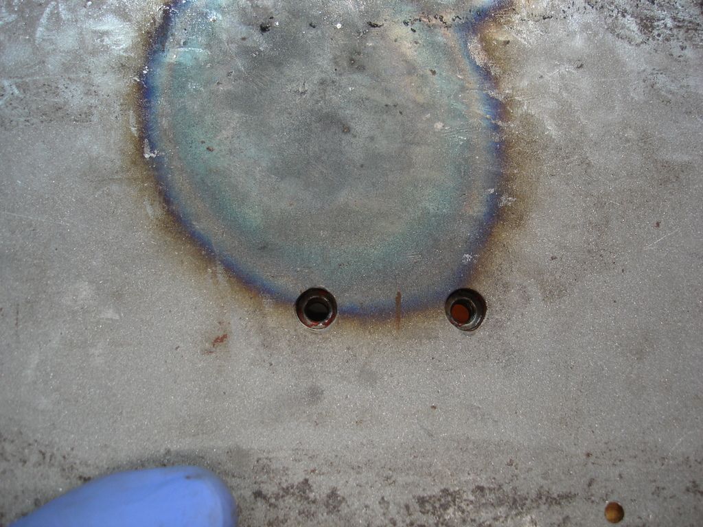
It took a while, but I managed to get the nuts centered in the scuttle holes.
Add the plates for the racing windscreens to each side of center.


The 2 side blocks were not think enough by about 1/8", so I had to add extra material to bring it up to level. I am using oak from Home depot, and applying the pieces with the grain cross-wise to the mahogany. This should help prevent the splitting that happened on the original insert.
Once the glue dried, it was just a matter of shaping the plates to the insert.
I apologize, as my camera is not doing well with auto-focus. Through the blur is the aluminum dash edge trim. Mine was damaged in the same accident that screwed up the left side of the car. The trim has to be straightened and then matched in contour to the insert and scuttle. So I dug the trim out of storage to get everything matched up at this point.
It was covered in white vinyl that did not age well.
Now you have a good view of the left end with the accident damage.
Compared to steel, aluminum is very easy to work. Here I am using the end of the anvil to re-shape the damaged area.
Once the general shape of the trim is good, I held it to the insert and marked where the tenax studs will be re-installed. These marks will give me a reference as I finesse the trim to fit the insert shape.

The lower edge of the trim will but the instrument panel. The top has to match the tenax holes. Then the contour is matched to the shape of the insert. So not difficult, but a lot has to line up!
Here is the finished insert.
Still going on the dash insert. It's quite the little body side job.

Here's the plate that holes the nuts for the rear view mirror.

It took a while, but I managed to get the nuts centered in the scuttle holes.


Add the plates for the racing windscreens to each side of center.


The 2 side blocks were not think enough by about 1/8", so I had to add extra material to bring it up to level. I am using oak from Home depot, and applying the pieces with the grain cross-wise to the mahogany. This should help prevent the splitting that happened on the original insert.

Once the glue dried, it was just a matter of shaping the plates to the insert.


I apologize, as my camera is not doing well with auto-focus. Through the blur is the aluminum dash edge trim. Mine was damaged in the same accident that screwed up the left side of the car. The trim has to be straightened and then matched in contour to the insert and scuttle. So I dug the trim out of storage to get everything matched up at this point.

It was covered in white vinyl that did not age well.

Now you have a good view of the left end with the accident damage.

Compared to steel, aluminum is very easy to work. Here I am using the end of the anvil to re-shape the damaged area.

Once the general shape of the trim is good, I held it to the insert and marked where the tenax studs will be re-installed. These marks will give me a reference as I finesse the trim to fit the insert shape.

The lower edge of the trim will but the instrument panel. The top has to match the tenax holes. Then the contour is matched to the shape of the insert. So not difficult, but a lot has to line up!

Here is the finished insert.
OP
CJD
Yoda
Online

I sand blasted the front clip to rough all the new patch panels to take the primer...at some future time.

This is one of the 2 bonnet hinge backing plates that I cut out many weeks back so I could straighten the scuttle. Now it's time to weld them back. I primed the area that will be against the scuttle.

And just clamped and welded back in place. I now had my son help me move the completed front clip upstairs in the house. I would prefer the shed, but the clip misses fitting in our SUV by 1". Hopefully it will only be for a few weeks?!?

I did forget...In this pic I have lain the instrument panel onto the insert.


That is what allowed me to locate the instrument panel mounting studs. This way I will be assured the studs will fit the panel slots perfectly when that time comes.


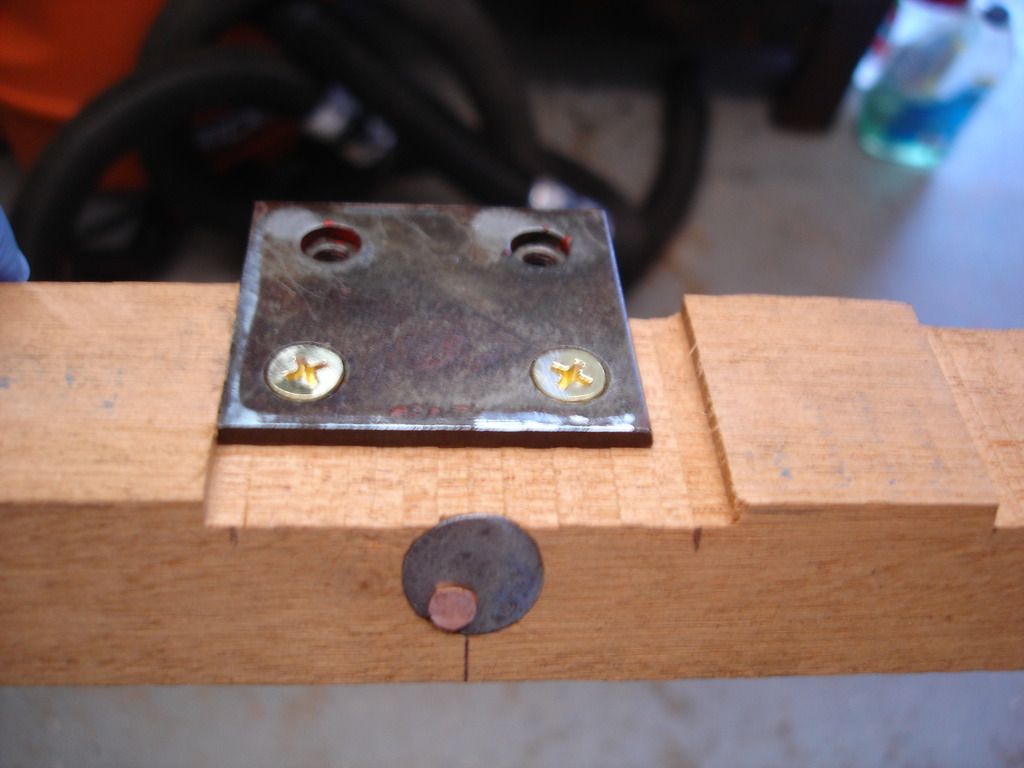
The final job for the week were those bent studs on the instrument end plates. Time to straighten those out!

Here I threaded a nut onto the studs and then heated the bent area red hot. The nut gives me something to tap with a hammer without ruining the threads.

In addition, I used a deep socket to prevent damaging my nuts. Always important to protect your nuts!

As always, every stud gets chased with a die to ensure no problems at assembly time.


And the finished product.


And here is the insert with the dash in position on the studs.
So that was it for the week. The front clip is history, so it is time to cut some more parts off the donor car to work on.
Once again, Cheers until next week!
M_Pied_Lourd
Darth Vader
Offline
Excellent work as always!
Cheers
Tush
Cheers
Tush