• Hey Guest!
    British Car Forum has been supporting enthusiasts for over 25 years by providing a great place to share our love for British cars. You can support our efforts by upgrading your membership for less than the dues of most car clubs. There are some perks with a member upgrade!

    **Upgrade Now**
    (PS: Upgraded members don't see this banner, nor will you see the Google ads that appear on the site.)
Tips
Tips

Aluminum Help Please

When you pulled the two halves apart, the spring loaded brushes popped out. Hopefully, you haven't busted them up. If you didn't, they are easy enough to reset.

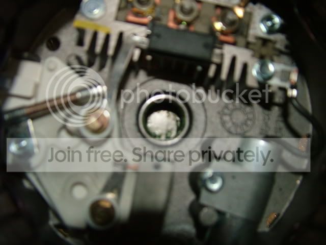
You need a paper clip that is straightened out. You have to put the springs (2 of them) back into the white plastic brush holder. Put the lower one in first. Then take the lower carbon brush and push it into the holder against the spring. Note the slots in the brush holder, and orient the brush so the wire slides in the slot. Now, while you're holding the brush in, insert the paper clip through the hole in the back of the alternator frame that aligns with the hole in the brush holder. Only push it in enough to capture the first brush. You might have to push the brush into the holder with a small screwdriver or pick to get it in far enough to get the paper clip in. Do the same for the next brush. The brushes will now be set in the holder, and you can assemble both halves. After the halves are assembled, pull the paper clip out from the back. You will hear the brushes click against the rotor, and all will be fine.

If you crushed the brushes, springs, and/or the brush holder, you will have to go to a local rebuilder and get some new pieces. If he's a nice guy, he will snicker and laugh only a little bit and give you a new, loaded brush holder.
 
Brushes were put back in proper order before rejoining the halves.
Any other idea.
Are all alt's clock able. I didn't mark the halves and I rejoined them to my satisfaction for remounting on the bracket?
 
Don,

Re-clocking a Delco alternator should have no affect on the rotor turning. The front half is locked down by the fan nut and the ball bearing that is in the front case.

The rear of the shaft, fits into a cupped needle bearing holder, that, exactly like universal joints, can have a needle drop down and may cause a binding on the shaft when re-assembled.

Put a paper clip down in the brush holder and pull it apart again. I'll bet you find a needle bearing laying on the bottom of the cup. If you have tightened the case halves together, you may see a bulge at the rear of the cup, or it may be pushed out.

Please don't ask me how I know this can happen to even a seasoned GM tech.
 
Did you take the rotor out of the drive end housing (front plate) when you cut the plate?? If you did, check to see that you have the proper spacers on the rotor. There is one that goes on the rotor before you put on the drive end, and one before you put on the fan. If either of those are missing, the rotor will bind up. IIRC, the thicker one goes on the rotor first.
 
martx-5 said:
Did you take the rotor out of the drive end housing (front plate) when you cut the plate?? If you did, check to see that you have the proper spacers on the rotor. There is one that goes on the rotor before you put on the drive end, and one before you put on the fan. If either of those are missing, the rotor will bind up. IIRC, the thicker one goes on the rotor first.
Yes the rotor came out with the top of the case. I did not see any spacers. I will check again.
What do they look like?
 
They're round spacers...like thick washers.
 
<div class="ubbcode-block"><div class="ubbcode-header">Quote:]Yes the rotor came out <u>with the top of the case</u>. I did not see any spacers. [/QUOTE]

Don,

I think that this is the key to the answer. From this statement, I'm assuming that you removed the 4 bolts and split the case, removing the front section with the fan and rotor all attached. The stator is bolted down in the rear half of the case, so that is solid.

You would have not seen any spacers unless you removed the rotor from the fan and separated it from the front section of the case.

Is that correct? If so, check for the dropped bearing in the rear cup.
 
Rear bearing is there. Does it ride in the roller bears or above. I did separate the rotor from the top case.
 
The very back of the rotor shafts rides directly in the rear roller bearing. The only things I can think of that would prevent to the rotor from turning when all assembled are...

1. Improperly or not installed brushes an/or springs in brush holder.
2. Spacers missing or not installed properly on rotor/front housing/fan/pulley assembly.
3. Something lodged in bottom of roller bearing.
4. Stator wires going to rectifier out of place.
5. Stator not sitting in housing properly.
6. Some metal piece stuck to pole shoe on outside of rotor and wedged into stator. The pole pieces often have a considerable amount of residual magnetism in them.

Pull the halves apart again. See if if the rotor spins freely in the drive housing. If it does, then the problem lies in the lower (back) half.
 
Don,

The rear end of the rotor shaft rides down in the red grease as shown in the second picture of my previous post.

I agree with Art on the next procedure(s)to follow if there are no dropped needle bearings in the cup and if you feel that the rotor turns freely in the front housing.

You would be surprised as to what can become attached magnetically to parts inside that housing. Look at everything very carefully when you have it apart.
 
I went back at it and still same deal. Could not see any top spacers. Seems the problem is it is not dropping into the bottom case deep enough.
TopBearing.jpg

BottomBearing.jpg

Bottomcasebearing.jpg

TopCoverBearing.jpg
 
Don,

Give me a picture of the fan on the front and the front of the case without it, if possible.

EDIT:

What is that thing sticking straight up from the capacitor on the right side below the rectifier bridge? It looks bent over, like something was forced against it.

And where is your brush holder? Actually, I see it, but where is the retainer holding back the brushes?
 
Don,

I'm trying to get a clear view of what appears to be a rivet head sticking up from the capacitor on the right. That should be a hex head bolt holding it down. I've downloaded your picture and blown it up, but it's just not clear enough.

If this is an optical illusion, forget it.

If whatever that is, is higher than the brush holder, then it will be hitting the rotor winding as is settles into the case and will cause a bind.

Let me know.
 
In the picture of the rotor, there is a spacer at the back by the slip ring. Take that off, it shouldn't be there. It is one of the spacers for the drive end. It looks like the one that should be on the OTHER end of the rotor shaft. There is also another spacer that goes between the bearing and the fan. IIRC the thinner one is on the fan side. In other words, there is a spacer on each side of the bearing in the front plate.
 
Art,

Do you mean like this (with cup bearing moved back, no spacer)?
 
That's exactly what I mean. There should be NO spacer back there.

Edit: I hope that when the two halves were screwed together initially, the force didn't move the slip ring down toward the rotor body. It doesn't take alot of force to move it. If it moved, then the brushes won't line up with the two segments on the slip ring. If you can wait until tomorrow, I can get a measurement at work. (I work for an electrical rebuilder) That slip ring could probably be pried up with a couple of screwdrivers if neccessary. The position isn't super critical. The brushes just have to ride on each segment.
 
Well, that would probably account for your problem with the binding Don.

I'm still curious about that thingy that "appears" to be sticking up from the capacitor, although I believe that Art has nailed it down. (No pun intended!)

Good night, Chet. Good night, David.
 
After another close look at the rotor, it doesn't appear that the slip ring moved. When they move, the two wires attached to it get kinda bunched up. Yours still look like they are OK.
 
The bottom bearing never came off. It slipped down to the bottom of the shaft and when I installed it, it went to the location it is now.
Paul- The brush retainer is a finish nail installed from the back side,you can't see it.
Art- What the heck is a slip ring?
 
The slip rings are the copper rings in the second photo from the top. They are the electrical rings that the brushes must ride on to make connection with the winds in the rotor. The steel shaft is the same size on both sides of the slip rings and the spacer is to the right of and touching the black insulator the slip rings are mounted to. The bearing is in the housing in the third picture. It is a needle roller bearing.
 
Back
Top