• Hi Guest!
    You can help ensure that British Car Forum (BCF) continues to provide a great place to engage in the British car hobby! If you find BCF a beneficial community, please consider supporting our efforts with a subscription.

    There are some perks with a member upgrade!
    **Upgrade Now**
    (PS: Subscribers don't see this gawd-aweful banner
Tips
Tips

after market steering wheel horn push set up

jvandyke

Luke Skywalker
Offline
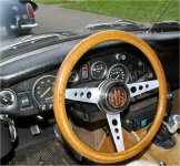
I want to, as part of my total dash re-do, set up the horn push. After market Moto lita "style" wheel, no contact ring, I was planning on simply running two wires out the back of the hub and leaving enough slack to allow the wire to wrap around the steering column during turning. Is this how it's done or what?
BTW oak dash, new coat of urethane, switches moved around, "pull start knob" returned (from POs push button starter and wired solenoid) "custom" 3D letters on knobs for IDing them, looking pretty darn nice....on the bench. Should end up with better ergonomics and aesthetics and lighting too.
 
I don't think you can leave enough slack in the wires. The problem is the number of turns you need... you have to have enough slack that you can turn the wheel all the way one direction and when you turn all the way the other... you can't have the wire bind up or get tangled in itself. Is there no way to add the contact ring to your set up?
 
dklawson said:
Is there no way to add the contact ring to your set up?

I don't think so. How is it normally done? Very common wheel swap I'm sure. The hub looks just like this from VB (although the wheel is a 4 spoke Moto-Lita looking thing like this (although it's not this exact wheel).
The new hub has a hole in the back. The push assembly itself is plastic and therefore won't provide a ground through anything. The backplate is metal but there's nothing on the hub side for it to ride on (like a ring). There's one wire with a bullet end coming out the back. So far I've soldered a wire to the backplate and was going to run both wires out the back along the column and then leave a bunch of slack to absorb the turns but that doesn't seem right. Where would you store that much slack so it wouldn't be a bother? I do have an original column shroud with a ring it. Likely I'm missing a bunch of parts from the boss kit? Or is horn push operation simply up to you? PO had mounted a push button the dash but that's not cool.
hornpush.JPG
 
There normally is a spring loaded contact, about half the diameter of a pencil that goes through a hole in the hub and makes contact with a brass ring that is affixed to the top of the column. Pressing the button shorts the horn to ground and the horn works. Look in the MOSS Catalog and you can see to horn contact push. The copper plate however may be NLA.
 
I dismantled a couple, let me check to see if I have any left over parts & pieces. The mention of the copper plate jogged my memory.
 
The Spitfire and GT6 use a similar spring loaded contact through the hub. On those cars it looks like a BIC pen tube with two pieces of brass tied together with a motor brush and spring.

Since you say you have an old column with the slip ring, perhaps you can buy or improvise the spring loaded contact to pass through the hole in the new hub. The lower end of the contact will ride along the slip ring. The top end needs to push against one side of the horn pushbutton's contacts. The other pushbutton contact will need to be connected to the hub itself to provide an earth connection.
 
I found this, no doubt I still have the little bag of bolts, nuts & springs around here somewhere.
If you can use any of it just pay postage and it's yours.
 

Attachments

  • 15440.jpg
    15440.jpg
    88.1 KB · Views: 789
Rick,

If he can't use it I certainly can, this is the missing piece I would need to change Bugsy my '68 from stalk mounted horn to center push horn.
 
I knew there was a reason I kept the pieces...
When I made my steering wheel center badge I didn't need any of the horn bits so I removed them.

I will dig around and see what else I can find.
 

Attachments

  • 15441.jpg
    15441.jpg
    99.2 KB · Views: 778
I think I understand how OEM would work: spring loaded contact sticks out the back of the hub and makes contact with the stationary ring mounted to the "shroud" (I'll call it) when pushed. I have a factory ring and shroud (not that it'll do me any good). In this aftermarket push though it would be grounded through?? Right now with a continuity tester on the red wire sticking out the back and the other probe on the push button's back plate, pressing the button closes the circuit. There is no mechanical action on the backside of the push button when pushing, so noway to have a little plunger contact "reach through" and contact a ring. I guess I don't get how these would normally be set up? Add a push button horn on the dash like the PO did?.....it worked, I just never found the button in time when I wanted to blast somebody.
 
How many turns lock to lock on these things? 3? Need some nice elastic wires!
 
<div class="ubbcode-block"><div class="ubbcode-header">Quote:]How many turns lock to lock on these things?[/QUOTE]

Sorry - don't know.

Here are the other parts I found, I will keep digging.
Seems these are not quite complete, a couple the rubber pieces and a nut missing maybe?

(just found one more, I'll keep looking)
 

Attachments

  • 15442.jpg
    15442.jpg
    95.3 KB · Views: 811
So the backside of the aftermarket horn pushbutton is metal and is connected to the red wire in your photo when pushed?
 
Whoever wants the parts I posted above send me a PM with a mailing address.
 
Yes, backside is one metal plate with that red wire sticking out. I could maybe ground the plate to the column (so far I soldered a wire on it to run all the way through) but I'll have to do something the other side of the circuit (red wire) anyway, so, yeah, I don't know. There's lots of these wheels out there, how do guys work the horn?
Here's my crude concept of an OEM set up? Sorta?
hornpushmaybe.jpg
 
I've seen folks uses a long curly flex cord think telephone handset cord wrapped around the column. Ugly but functional
 
I'll mess around with it, have to think that many have addressed this issue before. Maybe the proper boss kit made for this hub would work. Maybe I have a mismatch of pieces or something. This may sound stupid but slack behind the dash with some really light springs to hold the slack up until taken up, then released again? I don't know sounds pretty hokey. What's the diameter of the column? 1 1/2"? So, about 5" circumference, call it 4 turns, 20" of slack needed. Sounds plausible, I guess.....will certainly make me the DPO someday.
 
I like your sketch, it is very helpful.

What your sketch shows is what I'm familiar with on the Mini and the Triumphs I own. Your steering column should be grounded somewhere. Check that with a multimeter to confirm that it is.

The purple wire should be "hot" coming from the horn. You can test that by using a jumper wire to briefly connecting the purple wire to ground which should sound the horn.

So... if the column is grounded, you need to setup the system as your sketch shows with the following exceptions. Take a piece of double-sided foam mounting tape and put it on the back side of your horn pushbutton. The tape should only cover the hole in the middle of the steering wheel, you're not using this to attach the pushbutton in place. Cut a piece of brass shim stock perhaps 1/4" smaller in diameter than the opening in the steering wheel. Solder a crimp lug onto the brass disk and attach it to the double stick foam tape, then connect the red wire. Fit the hub and wheel to the car, insert the spring contact through the hub (and against the slip ring) and fit the horn pushbutton to the steering wheel.

The bottom end of the spring contact will be touching the slip ring for the horn. The top end of the spring contact will be against the brass shim disk. When you push the horn button it will provide the path to ground through the steering column.
 
Jim, there's a package on it's way to you.
 
That sketch was supposed to represent OEM setup in my mind (having never seen one, nor paid attention on other cars). This is what I'd have to do to replicate it with a slip ring. Essential difference is my aftermarket push has no mechanical means to "reach out and touch" a slip ring. So, as below, it would be in constant contact and the push would complete the circuit. Probably more hassle than just running wires and trying the "slack" method? I can't see myself making the slip rings and all, keeping the one on the back of the hub isolated from the hub, getting good contact all the time and not wearing it out right away? Or is this the way it "should" be done?
aftermarketpush.jpg
 
Back
Top