• Hi Guest!
    You can help ensure that British Car Forum (BCF) continues to provide a great place to engage in the British car hobby! If you find BCF a beneficial community, please consider supporting our efforts with a subscription.

    There are some perks with a member upgrade!
    **Upgrade Now**
    (PS: Subscribers don't see this gawd-aweful banner
Tips
Tips

MGB 1966 MGB Roadster - Flasher Issues

sjconant

Freshman Member
Country flag
Offline
Hello everyone-

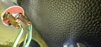
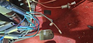
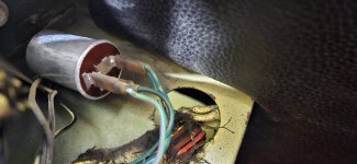
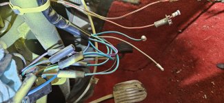
This is my first time and I am by no means a mechanic and trying to learn. One problem I have is that I cannot get my 1966 Roadster Blinkers to Work. I tried to search everywhere and I found that the Flasher Relay is under the Glovebox area. I was told to test the "Green" wires for power. IF there isnt any Power, that the "Hazard" switch is the issue. Here is the problem. I cannot find anywhere about where the Hazard switch is on this 1966 Roadster. Its not obvious to me. Keep in mind this car had all its electronic switches pulled by previous owner to repaint the whole car. Sadly they put some of it back not sure if everything was put back right. Anyways, I did replace the Blinker Control on the Steering column and reconnected them Color by color that I found on the Old one. The only thing missing is that this new one had a Brown Wire but there isnt a Brown to connect to under there. So I can provide pictures of my setup but I really could use some direction as to if there is a Hazard switch on this car and where it would be. Where the Flasher Relay is, there was a connector with 2 dark green wires, Another with a light Green, and antoher with Green with Red Stripe.
I really hope someone could guide me because that is the last electrical thing I need working. The Headlights work, Break lights, Running lights. I am just lost on the Turn signals.
 
Good morning and welcome!

If you don't already have this, here's a great and easy to read wiring diagram. Scroll down to the second page for your '66 B:


If memory serves, the flasher was mounted in much the same area through most of the model years - behind the glove box to the left of the wiper motor. Here's a write-up of the wiring:


Hope this helps!

Mickey
 
The wiring diagrams indicated in the previous post are worth their weight in gold to be certain. The hazard/directional system on these cars is pretty simple but not completely intuitive in how it works. I had to reconstruct most of the wiring for mine because previous owners cut away all of the connectors for the system so I spent a long time with a meter and test lamp getting whats left of my mind wrapped around how this thing works.

The key to the whole system is the hazard switch (which is located in the center lower section of the front panel near the cigar lighter). It has a 6 pin connector - 4 on one half and 2 on the other. 2 independant circuits go thru it and technically it is a selector switch, not a simple on-off. When it is set to the position marked "off", it actually turns ON the directional controls by bridging the pins on the 2 pin side. This allows power from the "hot-with-key-on" circuit to pass thrrough the directional flasher unit (normally under the dash near the wiper motor), over to the signal control switch on the column and then to the correct left or right side lamps. In this position all the pins on the 4 pin side are completely isolated from each other as well as the 2 pin side. If these 2 pins are not connected the left/directionals will not receive power, even if the directional flasher and column control switch are properly connected and in good condition.

When the hazard switch is flipped to the positon marked as "on", it disconnects the directional control flasher pins and bridges the all the pins on the 4 pin side, connecting the indicator lamps on both sides of the car together with an additional hazard indicator lamp (also in in the center section). In this position, power is drawn thru a seperate hazard flasher relay (also located in the center panel area, fed from an always hot circuit instead of the hot-with-key-on circuit). A brown wire on the alway-hot circuit comes thru a single in-line fuse holder to provide the power. Be careful with this circuit - the brown wire circuit is always hot and unfused (unlike the purple wire circuit which is always hot but protected by a fuse) - the only protection against a short circuit in the hazard system is that inline fuse.
 
Very nice, but a 66 B doesn’t have “hazard” lamps. Brown wire is a hot wire, so be careful. Green wire is ignition on power. Flasher will be a three wire configuration and is fitted with a 1/4” bolt.
 
Ooops - I was looking at a wrong year diagram. Didn't catch that there was no actual hazard flasher system on the 1964-1967 diagram at all until just now...so much for being helpful.
 
You were helpful!
Hazards came with the MKII, and you described it very well.
MKIs have a very simple circuit, save for the indicator lamps on the dash.
 
I appreciate all that you have given so far. Yes from the wiring image for the 66 I didnt see a Hazard inline anywhere. So that is why I was very stumped. So I am back to Square 1. I did a Flasher Relay Test by using a battery and a Bulb and found that even a New one just leaves the light on which from videos I watched, its supposed to blink that light correct? I bought this from Moss Motors btw and maybe these Round Relays dong work like that when you test them with power. The next Problem is that I disconnected the 2 Green to one PIN Wire and turned the ignition on but while putting the Ground to the Grounds that were mounted behind the relay (which i screwed back in for testing) and never once did I get any Voltage from the 2 Green to 1 PIN Connector. So I thought maybe its the light green wire instead and I didnt think it could possibly be the wire that is Green with a Stripe.... So to be clear, I also do not have the front bulbs in on the car but the back lights are wired in. I thought I read somewhere that if all the Bulbs were not wired in, it wouldnt work. Not sure if that is true or not. but regardless of all of that, Should I not be receiving Voltage from the Double Green Wires when the key is in the On Position but car not started?
 
I can try and take pictures of the Wiring and the Relay as well as how the connectors are on the Column Shifter for the Lights. There is one Brown wire left not connected from the Column but I couldnt find where that should go. Maybe that is another issue?
 
There is no relay fitted from the factory. The grn/wht and the grn/red are for left and right side turn circuits.
Solid green is feed wire. Would check the fuse panel for current. Also, there are wires between the tach and speedo for dash indicators.
Would fit bulbs and all wiring. Usually the light won’t blink without bulbs.
 
I am at a loss still. Hopefully these pictures can help someone answer this for me. So here is my run down. I have directly put battery power from Positive to all 4 Lights each. In fact, when I do a wire on the Left side front, it also turns on the back. So that tells me 2 things, One the wires are good front to back, and the Grounding is good. So then I went under the dash, ran a wire directly from the Positive side of the battery and put it inside the Green/Red Stripe wire and the lights came on. So that tells me also that power is going through those wires with no issues. I then used a Volt meter and turned on the ignition and got 12 volt then I put the Double Solid Green back into the "X" terminal since apparently the new one has X and not B (Unless this is the wrong type flasher from Moss Motors). then I put the Tester on the "L" and received 12 Volt. The Unmarked "on the wire schematics and on the flasher) and received no power. Not sure if this is on purpose or I missing something. Got these results on a new Flasher and the Original that I thought was bad. Here is my results. I NOW have the Left Indicator Light show up on the dash but stays solid. Switching to right has no light (but I dont know if the indicator on the right of the dash is out yet) BUT neither Left nor right Lights up on the car.... Hopefully with all of this information and the pictures, maybe someone can tell me what I am missing or what I can check next. This car is practically ready to go and this is the only thing keeping it from Drive Worthy on the road and I am ready to get out and drive this thing everywhere. THank you all in advance.
 

Attachments

  • 1000020606.jpg
    1000020606.jpg
    2.5 MB · Views: 3
  • 1000020608.jpg
    1000020608.jpg
    2.5 MB · Views: 2
  • 1000020605.jpg
    1000020605.jpg
    1.8 MB · Views: 3
  • 1000020607.jpg
    1000020607.jpg
    2.7 MB · Views: 2
Also, I do see this in the link someone provided above, But could someone walk me through the best way to test this and how? Like which two wires do I combine to test from the flasher? Where should I test voltage from the indicator switch to the Flasher?

->If you suspect the flasher unit itself just bridge its two contacts. The lights should light, but not flash.<- Which 2 wires?
 
I'm looking at the wiring diagram for the earlier cars right now, and yes I can see how this gets confusing. It looks like the instrument panel indicator lights are in fact a separate circuit from the actual front and rear lamps. The later flashers only had 2 contacts, which is why the tip of briding the 2 contacts doesn't make sense in your case.

Based on the wiring diagram, the connector with the 2 green wires is your incoming power from the key-on fuse - you should have +12 there at any point when the key is on.

The green wire with the brown stripe is the one that goes through your turn indicator switch then onto the front/rear lamps. The green wire with the purple stripe is is related to the instrument panel indicators (my guess is it feeds the pulsing 12 volts out on that wire through a set of secondary contacts at the turn signal switch and then to the selected panel indicator light).

If you disconnect the double green wire and the green with brown stripe wire, then connect those together that would be the 2 contacts that should allow the left or right front/rear lamps to come on (but not blink) when you make the selection at the switch. The panel indicators won't come on in that configuration from what I can tell. Again this is all just from studying the diagram - my car is much later and has a completely different system.
 
Back
Top