-
 Hi Guest!
You can help ensure that British Car Forum (BCF) continues to provide a great place to engage in the British car hobby! If you find BCF a beneficial community, please consider supporting our efforts with a subscription.
There are some perks with a member upgrade!**Upgrade Now**
(PS: Subscribers don't see this gawd-aweful banner

Tips
- We have a special forum called "Member Articles" where you can submit actual articles for consideration for publication. Learn More
- Don't have an Avatar? If not, your avatar will default to the 1st character in your username. Go into "Account Details" to change your Avatar.
- Some basic forum navigation info: click
 Hey - did you know if you click on the title of a thread it will take you to the first unread post since you last visited that thread?
- Hey Guest - Is your British Car Club in our Clubs database? If not, send me a PM - Basil

- Looking for a local club? Click the "Clubs" tab above and browse hundreds of clubs world-wide.
- Add Android or iPhone APP: click
- Did you know - any picture or video you add in your posts in any marque-specific forum will also get added to the Media Gallery automatically.
- A few more tips about posting and replying: click
- Hey there Guest - be sure to keep your profile page up to date with interesting info about yourself: learn more
- More tips and tricks on Posting and Replying: click
 but were afraid to ask:
  STOP!! Never post your email address in open forums. Bots can "harvest" your email! If you must share your email use a Private Message or use the
  smilie in place of the real @
- Want to mention another member in a post & get their attention? WATCH THIS

- So, you created a "Group" here at BCF and would like to invite other members to join? Watch this!
- Hey Guest - A post a day keeps Basil from visiting you in the small hours and putting a bat up your nightdress!
- Hey Guest - do you know of an upcoming British car event?
 Pretty Please - add it to our Events forum(s) and add to the calendar! >> Here's How <<
- Hey Guest - you be stylin' Change the look and feel of the forum to fit your taste. Check it out
- If you run across an inappropriate post, for example a post that breaks our rules or looks like it might be spam, you can report the post to the moderators: Learn More
- If you would like to try some different "looks" or styles for the site, scroll to the very bottom, on the left and click the Style Selector.
You are using an out of date browser. It may not display this or other websites correctly.
You should upgrade or use an alternative browser.
You should upgrade or use an alternative browser.
MGB Just bought a 1966 MGB
- Thread starter jjroth63
- Start date
Here is the update for 8/27/2023:
7/3, I bought the car
7/6, I returned the car for fake VIN and undisclosed problems
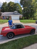
8/26. I bought the car, for a greatly reduced price, drove it 200 miles home on the expressway at speeds up to 75 MPH. I had zero problems with the drive, but I now have a car that needs a lot of attention.
I bought a 1966 MGB that has had some modifications done by amateurs. I will break my concerns into separate posts.
Please help me find the solutions, I am not a mechanic, but I have some skill and ability to think logically.
Thanks,
John
Chicago
7/3, I bought the car
7/6, I returned the car for fake VIN and undisclosed problems
8/26. I bought the car, for a greatly reduced price, drove it 200 miles home on the expressway at speeds up to 75 MPH. I had zero problems with the drive, but I now have a car that needs a lot of attention.
I bought a 1966 MGB that has had some modifications done by amateurs. I will break my concerns into separate posts.
Please help me find the solutions, I am not a mechanic, but I have some skill and ability to think logically.
Thanks,
John
Chicago
Attachments
Last edited:
The 1966 MGB has been converted to a negative ground, with an alternator.
My first issue of concern:
The turning signals do not work. The head lights, tail lights and running lights in front illuminate, the switch on the steering column has been replaced, none of the interior lights work.
I removed the interior light bulbs, they tested OK. I would like to replace all of the lights with LED.
Please help me trouble shoot the turning signals.
Thanks,
John
Chicago
Last edited:
The 1966 MGB has been converted to a negative ground, with an alternator.
My second priority is:
The horns do not work, the wires are marked but disconnected. When I test the wires at the horns, there is always 12v power, this must be wrong.
I tested the horns with a 12v battery and they work.
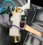
I pulled the steering wheel and there was an bad wire connection. The purple wire is too short inside of the steering column to make a proper connection to the horn switch. I will probably have to pull the purple wire back under the dash and splice in a new piece to give me the proper length.
What are my best option to fix the horns?
Thanks,
John
Chicago


My second priority is:
The horns do not work, the wires are marked but disconnected. When I test the wires at the horns, there is always 12v power, this must be wrong.
I tested the horns with a 12v battery and they work.
I pulled the steering wheel and there was an bad wire connection. The purple wire is too short inside of the steering column to make a proper connection to the horn switch. I will probably have to pull the purple wire back under the dash and splice in a new piece to give me the proper length.
What are my best option to fix the horns?
Thanks,
John
Chicago
Last edited:
The 1966 MGB has been converted to a negative ground, with an alternator.
Another priority are the electronic gauges:
Fuel gauge and odometer work.
Speedometer jumps around, hopefully a clean and lube will help.
The tachometer, oil pressure and water temperature gauges do not move.
Where should I start with the gauges?
Thanks,
John
Chicago


Another priority are the electronic gauges:
Fuel gauge and odometer work.
Speedometer jumps around, hopefully a clean and lube will help.
The tachometer, oil pressure and water temperature gauges do not move.
Where should I start with the gauges?
Thanks,
John
Chicago

Offline
The dual OP/temp gauge is mechanical, an ether bulb (expanding gas) for temp and a copper pipette from engine to gauge for oil pressure. Only has an electrical connection for an illuminating bulb. All dash lights are (or should be) on red/white stripe wires. Solid red to rheostat for power, out from that to instruments.
Offline
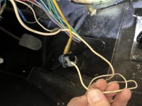
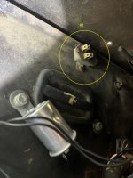
That cluster of dangling wires should be for the tach. It needs a couple slight mods to work accurately with a negative ground setup, not difficult. The white wire is the ignition from the switch to the coil, the tach works on induction pulse from that. The yellow wire is an "extra" circuit for an overdrive apparently not in your car, with the switch mounted in the opening to the left of the fuel gauge when fitted.
Offline
There are a lot of loose wires in this car.That cluster of dangling wires should be for the tach. It needs a couple slight mods to work accurately with a negative ground setup, not difficult. The white wire is the ignition from the switch to the coil, the tach works on induction pulse from that. The yellow wire is an "extra" circuit for an overdrive apparently not in your car, with the switch mounted in the opening to the left of the fuel gauge when fitted.
I need a little more help to make sure that I understand. I do not have overdrive, is the "plug" normal or is there something else that should be there?
are you saying the tach wire should be connected to the white wire?
Thanks
Is the rheostat the "P" knob between the tach and speedo?The dual OP/temp gauge is mechanical, an ether bulb (expanding gas) for temp and a copper pipette from engine to gauge for oil pressure. Only has an electrical connection for an illuminating bulb. All dash lights are (or should be) on red/white stripe wires. Solid red to rheostat for power, out from that to instruments.
What is the mechanical connection for the temp and pressure?
Offline
Have a look at the wiring diagram. The white wire should have a small loop around a plastic holder which is held to the back of the tach with a small metal "horseshoe" clip. For an induction pulse, not direct connection. That plug is something someone used to cover the hole for a switch if overdrive was installed. Otherwise the hole had a metal plug fitted.There are a lot of loose wires in this car.
I need a little more help to make sure that I understand. I do not have overdrive, is the "plug" normal or is there something else that should be there?
are you saying the tach wire should be connected to the white wire?
Yep. "P" is for panel... the instrument lights.Is the rheostat the "P" knob between the tach and speedo?
What is the mechanical connection for the temp and pressure?
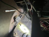
The temp and OP lines are routed thru the firewall to the engine compartment, yours are likely cut or not connected. Too many jackleg "mechanics" have no idea what they're doing, or consider it too much trouble to do it correctly. Some photos coming in a bit.
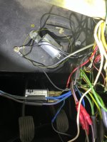
I found a purple/ black in the turning signal switch harness, but it runs into the "loom" and under the hood I would think. I cannot find the other end of the one in the steering column, or is it soldered into the column and the brush connects it to the car?
I found the white and yellow wires.
What is the block?
It looks like one of the flashers is disconnected.
What is the :mount" thing behind the stereo?
Thanks,
John
Attachments
CARSINC
Senior Member
Offline
Strip all the Lucas wiring out.The 1966 MGB has been converted to a negative ground, with an alternator.
My first issue of concern:
The turning signals do not work. The head lights, tail lights and running lights in front illuminate, the switch on the steering column has been replaced, none of the interior lights work.
I removed the interior light bulbs, they tested OK. I would like to replace all of the lights with LED.
Please help me trouble shoot the turning signals.
Thanks,
John
Chicago
View attachment 91862View attachment 91863View attachment 91864View attachment 91865View attachment 91866View attachment 91867
Buy a Painless wiring harness and install it.
Buy and install all electrical gauges from Speedhut.
where does the painless come from, Summit does not have oneStrip all the Lucas wiring out.
Buy a Painless wiring harness and install it.
Buy and install all electrical gauges from Speedhut.

Offline
Or you can go with an original harness from British Wiring.where does the painless come from, Summit does not have one
CARSINC
Senior Member
Offline
Painless Performance Products or, Rebel Wire.where does the painless come from, Summit does not have one
Just order a generic or hotrod kit
CARSINC
Senior Member
Offline
If you want a true British wiring harness, I've got a sparePainless Performance Products or, Rebel Wire.
Just order a generic or hotrod kit
I do not know anything about these, what is the time commitment to install? probably less than running down the problems.If you want a true British wiring harness, I've got a spare
CARSINC
Senior Member
Offline
You're correct. Forget the wiring harness. Just chase down and fix each problem created by the Dark Lord, Baron Verladimer von LucasI do not know anything about these, what is the time commitment to install? probably less than running down the problems.