-
 Hi Guest!
You can help ensure that British Car Forum (BCF) continues to provide a great place to engage in the British car hobby! If you find BCF a beneficial community, please consider supporting our efforts with a subscription.
There are some perks with a member upgrade!**Upgrade Now**
(PS: Subscribers don't see this gawd-aweful banner

Tips
- We have a special forum called "Member Articles" where you can submit actual articles for consideration for publication. Learn More
- Don't have an Avatar? If not, your avatar will default to the 1st character in your username. Go into "Account Details" to change your Avatar.
- Some basic forum navigation info: click
 Hey - did you know if you click on the title of a thread it will take you to the first unread post since you last visited that thread?
- Hey Guest - Is your British Car Club in our Clubs database? If not, send me a PM - Basil

- Looking for a local club? Click the "Clubs" tab above and browse hundreds of clubs world-wide.
- Add Android or iPhone APP: click
- Did you know - any picture or video you add in your posts in any marque-specific forum will also get added to the Media Gallery automatically.
- A few more tips about posting and replying: click
- Hey there Guest - be sure to keep your profile page up to date with interesting info about yourself: learn more
- More tips and tricks on Posting and Replying: click
 but were afraid to ask:
  STOP!! Never post your email address in open forums. Bots can "harvest" your email! If you must share your email use a Private Message or use the
  smilie in place of the real @
- Want to mention another member in a post & get their attention? WATCH THIS

- So, you created a "Group" here at BCF and would like to invite other members to join? Watch this!
- Hey Guest - A post a day keeps Basil from visiting you in the small hours and putting a bat up your nightdress!
- Hey Guest - do you know of an upcoming British car event?
 Pretty Please - add it to our Events forum(s) and add to the calendar! >> Here's How <<
- Hey Guest - you be stylin' Change the look and feel of the forum to fit your taste. Check it out
- If you run across an inappropriate post, for example a post that breaks our rules or looks like it might be spam, you can report the post to the moderators: Learn More
- If you would like to try some different "looks" or styles for the site, scroll to the very bottom, on the left and click the Style Selector.
You are using an out of date browser. It may not display this or other websites correctly.
You should upgrade or use an alternative browser.
You should upgrade or use an alternative browser.
TR4/4A Tackling the biggest problem with my TR4A.... Frame Damage :[
- Thread starter Djoslyn
- Start date
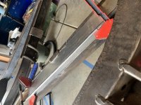
I picked up way more 14 gauge steel than I needed on friday. I guess extra never hurts
I got my first patches made yesterday. No welding yet though. I still need to pick up a tank and shielding gas for my welder..
I got my first patches made yesterday. No welding yet though. I still need to pick up a tank and shielding gas for my welder..
Attachments
I've been continuing to cut out rusty patches as I find them and create patches for those spots. All the while I've been practicing my welding skills. Today I've finally started welding in some of those patches into the frame!
I'm still debating on whether I should use some rust converter before I start closing in these sections of frame or just using some of the eastwood internal frame coating. I think I want to end up using both for the areas I open up for sure.
I'm still debating on whether I should use some rust converter before I start closing in these sections of frame or just using some of the eastwood internal frame coating. I think I want to end up using both for the areas I open up for sure.
Attachments
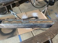
Got some more patches welded in today. I'm getting as much practice in in the front sections before I do some more extensive work on the trailing frame rails. Grinding the welds flush will get done later.
Attachments
Considered yes. I've leveled it up on some jack stands for the time being. I'm being careful about not over heating anything too much as I'm spot welding these panels into place. Hopefully this will be enough to keep anything from warping too much.
This frame has already had the front passenger corner replaced from a donor frame at some point in the past. I plan on taking it to a frame shop to bring that corner back into spec as that turret was bent about a 1/4" rearward already...
This frame has already had the front passenger corner replaced from a donor frame at some point in the past. I plan on taking it to a frame shop to bring that corner back into spec as that turret was bent about a 1/4" rearward already...

The major repairs are almost complete. I ran out of shielding gas over the weekend so I'll have to get more before I can finish these welds. I still need to find a local frame shop that will true up the twist in the frame. Once done I'll be adding the typical re-reinforcements before painting.
Attachments

Madflyer
Jedi Knight
Offline
I did a frame off restoration as the car I got had poor frame clip work LH side front. I replaced frame from a parts car that I got for $ 150.00 As there are few mounting points for body and most all elect. is in the body fuel and brake lines and steering and battery are about it. I added a hook assy at the garage supports for the rear and hooked the hood rails in front. I did have to move the frame side ways as garage role up door would hit hanger. When replacing body to frame I used long bolts with heads cut off as pins to line body as I lowered it. I did it myself remember doors will need to be adjusted and old mount spacers will not be the same.
The Robert Bentley TR book has all frame spec. to check for true. Ounce you see your old frame that would be the call as to replace or repair. A new frame needs everything mounted as repairing yours can be a lot less work
Weak points are at rear spring mount, shock mounts, Diff supports and rear swing arms .
GOOD LUCK and send pic of work .. Madflyer
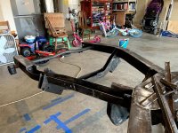
Finally some more progress!
I took a break from this over the winter and started looking hard for a shop that would be willing to check the frame for twist/straightness/etc. Unfortunately none were willing to work on just a bare frame as they have no good way to anchor it down besides chains. I found one that supposedly specialized fixing up these older cars and the measurements I"d done last year he seemed to think that it wasn't a big deal and I should just use it as is.
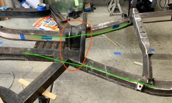
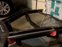
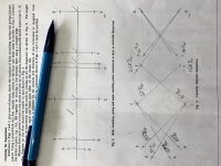
I started thinking though. I've done a lot more research on working with car frames over the last several months and I'd also gotten a handy laser level for another project. So I went ahead and measured everything again. This time I used the laser level to get the frame perfectly level front to back and side to side based on the central body mounts as they would have been farthest away from any accident damage in the past. Once done I re-adjusted the laser level to where the datum should be and started measuring all the crucial points stated in the manual.
Thankfully all the major suspension and body mount points in the front where I thought was twist were within a few mm of each other compared to the datum! It turns out what I thought was frame twist was a difference in the vertical height of the frame rail corner that had been replaced. That corner was different enough that sitting on my garage floor it can rock making it seem like there was twist in the frame.
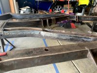
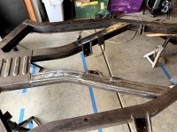
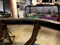
Unfortunately though. The extensive rust repairs I'd made in the rear bottom side of the frame ended up pulling the frame rails behind the drive shaft loop down. Measuring at the rear leaf spring mount it was right around 1inch lower than where it should be..
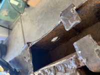
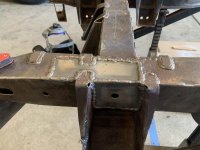
Since No shop was willing to take my money and help get the frame right, I figured out a way I could do it myself. I figured since cutting and welding on the bottom side of the frame pulled everything down, doing the same on the top side should correct it to some extent. I did run the idea by a friend of mine who has a good amount of car fabrication experience and he agreed it should work. I planned on re-inforcing the frame rails in that area with extra metal anyways to take care of the typical weak points so I shouldn't have to worry about weakening the structure with the cutting and re-welding.
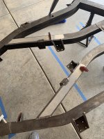
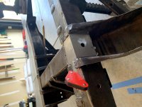
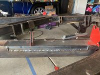
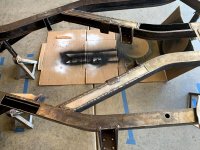
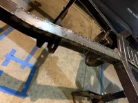
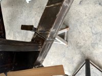
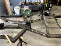
Anyways, today I ended up marking the top side and sides of the frame rails on each side. I cut through the top and sides down to about 1/4 of an inch from the bottom of the frame rail. I used some extra jack stands and some of those wooden wedges to lift the rear end of the frame back up to where it needed to be. I made a couple of tack welds at first and re-measured everything.
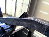
I did set everything about 1/8th of an inch too low from the spec in the manual because I knew as the welds cool it might pull up the frame in that area even more. Which it did.. by about 1/8th of an inch... So now the rear leaf spring mounts are a touch too high. But that can be taken care of with shims. Plus as I weld in the extra re-inforcements I'll weigh the rear end of the frame down and hopefully get it just right.
I've started making the cardboard templates for the various places I'll be adding more metal to the frame.
And just to make sure.. I measured every cross dimension just to make sure I still have a square frame after all of this work I've done.
I took a break from this over the winter and started looking hard for a shop that would be willing to check the frame for twist/straightness/etc. Unfortunately none were willing to work on just a bare frame as they have no good way to anchor it down besides chains. I found one that supposedly specialized fixing up these older cars and the measurements I"d done last year he seemed to think that it wasn't a big deal and I should just use it as is.
I started thinking though. I've done a lot more research on working with car frames over the last several months and I'd also gotten a handy laser level for another project. So I went ahead and measured everything again. This time I used the laser level to get the frame perfectly level front to back and side to side based on the central body mounts as they would have been farthest away from any accident damage in the past. Once done I re-adjusted the laser level to where the datum should be and started measuring all the crucial points stated in the manual.
Thankfully all the major suspension and body mount points in the front where I thought was twist were within a few mm of each other compared to the datum! It turns out what I thought was frame twist was a difference in the vertical height of the frame rail corner that had been replaced. That corner was different enough that sitting on my garage floor it can rock making it seem like there was twist in the frame.
Unfortunately though. The extensive rust repairs I'd made in the rear bottom side of the frame ended up pulling the frame rails behind the drive shaft loop down. Measuring at the rear leaf spring mount it was right around 1inch lower than where it should be..
Since No shop was willing to take my money and help get the frame right, I figured out a way I could do it myself. I figured since cutting and welding on the bottom side of the frame pulled everything down, doing the same on the top side should correct it to some extent. I did run the idea by a friend of mine who has a good amount of car fabrication experience and he agreed it should work. I planned on re-inforcing the frame rails in that area with extra metal anyways to take care of the typical weak points so I shouldn't have to worry about weakening the structure with the cutting and re-welding.
Anyways, today I ended up marking the top side and sides of the frame rails on each side. I cut through the top and sides down to about 1/4 of an inch from the bottom of the frame rail. I used some extra jack stands and some of those wooden wedges to lift the rear end of the frame back up to where it needed to be. I made a couple of tack welds at first and re-measured everything.
I did set everything about 1/8th of an inch too low from the spec in the manual because I knew as the welds cool it might pull up the frame in that area even more. Which it did.. by about 1/8th of an inch... So now the rear leaf spring mounts are a touch too high. But that can be taken care of with shims. Plus as I weld in the extra re-inforcements I'll weigh the rear end of the frame down and hopefully get it just right.
I've started making the cardboard templates for the various places I'll be adding more metal to the frame.
And just to make sure.. I measured every cross dimension just to make sure I still have a square frame after all of this work I've done.
Attachments

Offline
Here's a possibility on eBay:

Triumph TR4 • Original Frame Assembly | eBay
Find many great new & used options and get the best deals for Triumph TR4 • Original Frame Assembly at the best online prices at eBay! Free shipping for many products!
www.ebay.com
Offline
My apologies as I sent my message before seeing your last message today. Good luck!