• Hi Guest!
    You can help ensure that British Car Forum (BCF) continues to provide a great place to engage in the British car hobby! If you find BCF a beneficial community, please consider supporting our efforts with a subscription.

    There are some perks with a member upgrade!
    **Upgrade Now**
    (PS: Subscribers don't see this gawd-aweful banner
Tips
Tips

Help need reinstating my heater - BT7

fishyboy

Jedi Hopeful
Country flag
Offline
Hi all,
A few years ago the heater control valve on my BT7 started to leak. I bought several new parts but never got around to fixing it. Instead I just by-passed the heater.
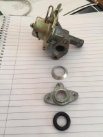
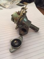
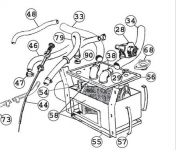
Now I would like to get the heater back working. The parts diagram only helps so far. I am looking for a bit of detail on how my parts go back together. I have parts 28, 29 and 68 shown in the first figure. Any ideas?

Thanks
Phil
Heather.png
IMG_4242 copy.jpg
 
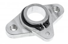
Phil - I had mine apart <2 years ago when I rebuilt my engine. The flange in your photo is upside down. The part we're seeing goes down toward the heater core. You should have two o-rings (117).

Attach the flange to the top with the middle screw. Locate lower o-ring onto flange protruding from lower side of heater top, as you lower top over heater stub pipe. Assemble top to sides of heater with clamps (96).

With the heater top clamped in place, seat the upper o-ring over the stub in the beveled recess in the flange. Screw the valve in place on the flange. Use screws long enough to reach through the flange to the captive nuts in the heater top.
Moss dwg more detailed; see this for full dwg:
https://mossmotors.com/austin-healey-100-100-6-3000/heater/heaters


screenshot.1669.jpg


The upper mounting screws at the ends of the angled mounts - these are difficult to deal with. With the heater out, I found it helpful to rig up studs on the car itself. I attached u-nuts to the mounting flanges with 10-24 screws in them as studs, pointing to the rear. That way when you offer up the heater, you can hang it off the studs while you install the nuts.

screenshot.1670.jpg
screenshot.1671.jpg
heater hose lengths and arrangement.

PS - suggest having a radiator shop pressure test the heater core to 10 psi (max) before installing.
 
Last edited:
I last worked on a Healey's heater in 1986, but I understand how a gland seal works. In essence, the two (2) flanges are bolted together to compress the rubber seal around the heater core's tube outlet/inlet.

I'd put the loose aluminum flange onto the core's tube, followed by the conical washer ("hollow side" up, to meet the rubber seal), then the seal, and finally, the valve. As far as tightening of the bolts go, just sufficient enough to prevent them loosening up__there may still be movement between the valve/gland assembly and the tube__probably some good lock-washers (internal or external 10-star type) would be an asset here.

As far as which way to orientate the valve port and cable connections, I haven't a clue beyond what's seen in the diagram. Sorry, no pictures of this assembly in my gallery (shocking, I know)!

EDIT: Looks like Steve has a better understanding of it (I didn't even remember there were captive nuts in the core's box...)!
 
You do not need a radiator shop to test a heater core. I have tested many by blocking one outlet and installing an air valve at the other. Put in 10 or 15 pounds pressure with an air hose and gauge and then dip in water tank to see if it leaks. Sometimes, if it leaks, it is in a place where you can solder a repair.
 
You do not need a radiator shop to test a heater core. I have tested many by blocking one outlet and installing an air valve at the other. Put in 10 or 15 pounds pressure with an air hose and gauge and then dip in water tank to see if it leaks. Sometimes, if it leaks, it is in a place where you can solder a repair.

Curt - welcome to the Forum. What kind of Healey do you have?
 
Back
Top