• Hi Guest!
    You can help ensure that British Car Forum (BCF) continues to provide a great place to engage in the British car hobby! If you find BCF a beneficial community, please consider supporting our efforts with a subscription.

    There are some perks with a member upgrade!
    **Upgrade Now**
    (PS: Subscribers don't see this gawd-aweful banner
Tips
Tips

TR2/3/3A Where is best spot to check temp with infrared thermometer?

TuffTR250

Jedi Warrior
Country flag
Offline
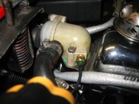
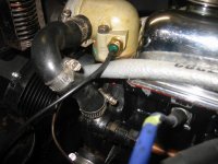
Where is the best spot to check engine temperature with an infrared thermometer? I've attached a couple of pictures with two ideas. Are there better more accurate locations? Note the red dots from the infrared thermometer in the pictures. One beside the sending unit and one down below the sending unit. Thanks!
Bob
 

Attachments

  • IMG_7071.jpg
    IMG_7071.jpg
    55.3 KB · Views: 277
  • IMG_7072.jpg
    IMG_7072.jpg
    59.5 KB · Views: 240
I think it depends on what part of the engine you want to check!

Coolant? Head, Block, Valve cover? etc. All will have different temps.

An infrared thermometer only checks the *surface* of what it's aimed at.

Just my two cents.
Tom M.
 
Infrared thermometers are very inaccurate when shooting old aluminum. If you want to know the temperature of the thermostat housing, put a spot of paint or piece of masking tape on it, and shoot that.

The water pump gets cooler water back from the radiator, so it should be cooler than the thermostat (which sees hot water leaving the engine). How much cooler depends on things like how much airflow there is through the radiator, and how far open the thermostat is.
 
I should have explained. I put in an electric temperature gauge instead of the capillary tube type. I've "bench" tested/measured the gauge and it seems to read a bit high. So I'm trying to determine what the water temperature is at the sending unit. Sounds like the best spot would be on the thermostat housing close to the sending unit. Would black paint be the best color for that? I don't have a problem with painting a good size spot on the thermostat housing. Thanks!
Bob
 
The color of the paint shouldn't matter. Basically, they are all black in the infrared spectrum, which is what the thermometer "sees".
 
,,,I don't have a problem with painting a good size spot on the thermostat housing.

That's what I did. No photo handy of it on the TR but here it is on another car:

2xbAu2l.jpg


I was wanting to back-stop the temp gauge so I selected a spot near the sender. I agree color doesn't matter but I think you'll want a flat paint to avoid picking up a reflection.
 
Thank you! Geo, I like your idea of a large black circle. It looks like it could have been put on by the manufacturer.
Bob
 
It's been ages since I had to do any really serious pyrometry work but what you effectively are dealing with is a single color infrared pyrometer. The two major factors in the accuracy of any temperature reading that you get from this type of instrument is the emissivity of the object being measured and the field of view. Emissivity is a function of the amount of energy radiating from a perfect "black body" that has an emissivity of 1.0 vs the amount of energy radiating from the object of interest at the same temperature. Nice shiny stuff will have low emissivity values while rougher and darker stuff will have high emissivity values. Hence the dark spot in Geo Hahn's post as most painted surfaces, organic materials and oxidized surfaces have emissivities in .9 to .95 range. Some infrared pyrometers have adjustments to correct for emissivity and that helps as long as you have a feel for the emissivity of the material you are dealing with and the temperature range you are trying to measure since wavelength is a fourth power function of temperature. In general for the type of temperature and resultant wavelength that we would see on a car I would use the following emissivity values as a rough guide if your instrument allows emissivity values to be adjusted:

Cast Iron - painted black .9 -.95
Cast Iron - unpainted and not corroded (say a brake rotor surface) .35
Aluminum - polished .04 - .10
Aluminum - oxidized .4
Stainless - bare, lots of variation depending on family and specific alloy .2 - .85

Field of view is the cone angle at which the instrument operates and is driven by the optics of the instrument. Your pyrometer should have instructions on focal lengths and spot sizes to obtain the most accurate temperature measurement. The issue is that the instrument takes an average of everything in the field of view, if your spot size includes other things at different temperatures or emissivities within the field of view, then the accuracy of your reading suffers accordingly. If you know the focal length and the distance to spot size ratio, you can position your instrument accordingly to obtain a more accurate reading.

Something else to consider is that some pyrometers and some multimeters also have a provision to connect a thermocouple, typically a Type K. If you have either tool featuring this provision, you could also use that as secondary or tertiary means of temperature measurement.
 
But, higher is NOT necessarily better in this context. All IR thermometers have a correction for emissivity; on most of the cheaper ones, the correction is either totally fixed, or not calibrated. (By which I mean there is a screw you can turn, but no indication of where say, 0.95 is vs 0.90.)

So to get the correct reading on the display, you need to either match whatever the thermometer is calibrated to, or calibrate the meter to match the surface. That means you need to know both the surface emissivity, and what the meter is set to.

Of course, there is a calculation you can make when the two numbers don't match, but you still have to know the numbers.

Here's a chart with a few values listed
https://www.engineeringtoolbox.com/emissivity-coefficients-d_447.html
 
Ah ... but where is the best spot to check the engine temp?

Define "engine temp".

Seriously, the temperature varies all over the place on a running engine, and even for hours after it is shut down. To talk about checking "engine temp", you have to be more explicit about what you actually want to check. Just for an example, the exhaust valve heads can reach 1000F on a hard working engine (even a relatively low performance one).

Most often, perhaps, we are interested in coolant temperature; but as I mentioned before, even that is by no means constant throughout the engine.

I certainly would not call it normal, but I have seen an engine boil over, while the coolant in the radiator was still frozen.
 
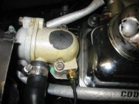
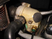
I am trying to determine how close together the temperatures are between what the electric temperature gauge I installed is showing and the coolant temperature that the Infrared thermometer says it is by the gauge sending unit. I'm planning to paint a flat black dot on the thermostat housing. My Etekcity infrared thermometer says it is fixed at 97 emissivity and the table above from Full Twisting says flat black lacquer paint emissivity is 97. So from what I understand that should work. Attached are pictures of my two paper mock up ideas on where I should place the black dot to do what I'm attempting. Which is "best" of these two? Will they both work? Thanks!
Bob

IMG_7073.jpgIMG_7074.jpg
 
Bob - the thermostat is measuring the temperature of the coolant at the point where the thermostat sensor is located.

So if your infrared gadget is measuring the *exterior* of that housing, you'll never really know how it relates to the interior coolant temperature. The ambient temperature also changes the temperature of the exterior of the housing.

The two devices (i/r thermometer and the car's temp gauge) are always measuring two different things. The "black spot" where the i/r is focused, isn't going to tell you the temperature of what's inside the pipe.

Tom M.
 
If you want to check the accuracy of your new electric gauge, why not just put the sensor into a can of hot water along with another thermometer or two? (meat thermometer, candy thermometer, another car temp gauge, etc.)

At least then you'll have an idea of how the electric gauge compares to other devices *measuring the same thing*.

TM
 
Either of those spots should work fine within the limitations of what you are doing.

Other places where measurements may be useful include:

Radiator (checking how much temps drop from top to bottom)

Radiator (looking for cool areas that may suggest blockage)

Exhaust manifold (a colder cylinder right after start-up may confirm fuel starvation or ignition failure)

Thermostat housing and top hose (comparing the two may show when the thermostat starts to open)

Brake discs/drums (a hotter one may indicate brake drag)

Lots of other places, those are just some I recall off hand.
 
I agree with Geo; either location will work fine. Yes, there will be some small difference in temperature between the surface of the housing, and the coolant flowing inside, but it won't be enough to worry about.

The pan of hot water works too; but still has uncertainties. When you get into the range of interest (around 180F), the surface of the water loses a lot of heat due to evaporation. Unless you're careful, you'll wind up with significant heat gradients within the water.

If you're using a TR4 type temperature gauge, they also respond so slowly that it's difficult to hold the temperature of the water constant long enough for the gauge reading to stabilize. In effect, the temp gauge doesn't give you the temperature right now, but rather a weighted average over the past several minutes.

And you still get to worry about the accuracy of the 'reference' thermometer. Etc, etc
 
Back
Top