• The Roadster Factory Recovery Fund - Friends, as you may have heard, The Roadster Factory, a respected British Car Parts business in PA, suffered a total loss in a fire on Christmas Day. Read about it, discuss or ask questions >> HERE. The Triumph Register of America is sponsoring a fund raiser to help TRF get back on their feet. If you can help, vist >> their GoFundMe page.
  • Hey there Guest!
    If you enjoy BCF and find our forum a useful resource, if you appreciate not having ads pop up all over the place and you want to ensure we can stay online - Please consider supporting with an "optional" low-cost annual subscription.
    **Upgrade Now**
    (PS: Subscribers don't see this UGLY banner)
Tips
Tips

Watson Mechanical Brake Light Switch

AUSMHLY

Obi Wan
Country flag
Offline
Heads up to all those who installed the Watson mechanical brake light switch. It will wear out and stop working.

I opened the unit up to find out why it wasn't working.
There are two brass electrical plugs on the outside of the unit. Inside of the case those plugs are flush with the surface of the black plastic plate.
The lever arm moves a brass contact with two protruding points till they come in contact with the two flush brass plugs ends. Over time the siding plate makes a grove in both the plastic and the brass plug ends.
Once it's worn, sometimes it makes full contact sometime it gets hung up and doesn't. No contact, no brake lights.

I filed the grove out of the plastic and the two brass contacts. Now it works like new. However because of the design, it will eventually wear out again.

I'm going to change the Watson light switch out to a metal door jam pin style. Those don't wear out.
Photos of each below.
Watson is with the arm. Door pin is straight
View attachment 36970View attachment 36971
 
Last edited:

steveg

Yoda
Gold
Country flag
Offline
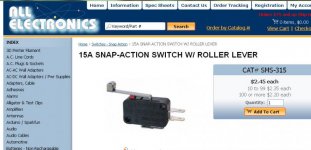
I've been using this one as a mechanical brake light switch since 2006:
https://www.allelectronics.com/make.../15a-snap-action-switch-w/roller-lever/1.html

BrakeLightSwitch.jpg

Comments -
Could one put a capacitor across the switch to prevent arcing as that's probably what erodes the contacts?
Using the switch to fire a relay would also likely make the points last longer.
If we opened the doors as often as we put on the brakes, maybe the door switch would wear out faster than the brake light switch.
 
OP
AUSMHLY

AUSMHLY

Obi Wan
Country flag
Offline
I've been using this one as a mechanical brake light switch since 2006:
https://www.allelectronics.com/make.../15a-snap-action-switch-w/roller-lever/1.html

View attachment 36972

Comments -
Could one put a capacitor across the switch to prevent arcing as that's probably what erodes the contacts?
Using the switch to fire a relay would also likely make the points last longer.
If we opened the doors as often as we put on the brakes, maybe the door switch would wear out faster than the brake light switch.

The problem with the watson is physical wear. It grinds a grove in the plastic and brass. Then it starts hanging up and not moving freely.

I wonder if the door pin switch will arc and wear out. Good point. What do others think?

Which switch are you referenceing in reguards to using a capacitor?
Are you using a capacitor or relay with your switch?

Steve your switch looks like a good solution. Could you post some photos of where and how you mounted it?
Thank you for providing the purchase link.
 

steveg

Yoda
Gold
Country flag
Offline
The problem with the watson is physical wear. It grinds a grove in the plastic and brass. Then it starts hanging up and not moving freely.

I wonder if the door pin switch will arc and wear out. Good point. What do others think?

Which switch are you referenceing in reguards to using a capacitor?
Are you using a capacitor or relay with your switch?

Steve your switch looks like a good solution. Could you post some photos of where and how you mounted it?
Thank you for providing the purchase link.

Years ago a Corvair club magazine article showed how to put a capacitor across the points on the electric clock to prevent arcing and quick-erosion of the points.
Would guess the capacitor used on the fuel pumps would be the same. This would work on any switch.

I'm not currently using either a capacitor or relay with this switch as I haven't had a problem yet.

Not sure how a capacitor or relay would interact with the flasher relay. Maybe no problem if the relay were close to the brake switch - the answer here may have to be developed through experimentation.

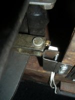
Brake switch is mounted on an adjustable bracket on the leading edge flange of the heater plenum such that the arm roller interacts with the rear of the brake clevis. See:
https://www.pbase.com/stevegerow/image/70570849
and preceding couple of images.
BrakeSwitchMount.jpg
 

Keoke

Great Pumpkin
Country flag
Offline
Well as Ausmhly pointed out his switch failure was due to a mechanical faiure of the switch components.

Adding a Capacitor across this type circuit will not add much to the circuits reliability as its characteristic is more on the resistive side.

Similarly, Relay switching is more often relegated to high current or inductive circuits switched by low curent devices-hand operated switches- and are not generally required in this type circuit either,
 
Country flag
Offline
And why was the original hydraulic switch deleted? My BN6 is still energizing its brake lights with a something '58 date-coded switch, and problem-free.

If you don't trust the hydraulic pressure switch, rather than delete it, you could wire your mechanical do-dad in parallel with it (either/or would complete the circuit). By the characteristic of their response times, the mechanical switch would close first, and break (or open) first, thereby halving the potential for arc degradation__in theory! In reality, the current draw from those low wattage bulbs is a non-issue.

I did however, add a second hydraulic pressure switch (same OEM design) @ the rear axle, by substituting a 4-way** connector, to activate a 3rd l.e.d. brake light that's incorporated into my billet aluminum license plate frame. Power for the circuit was provided via the switched 12VDC+ from the nearby fuel pump. The benefit of a redundant circuit being one thing, but the truth is, I didn't want to confuse the combined brake light/turn signal function relay!

IMG_7774.jpg


** it's actually a 5-way, with one (1) port plugged; happened to be something I had on hand.
 

steveg

Yoda
Gold
Country flag
Offline
I went with the mechanical switch when my original started leaking because: 1) bad reputation of replacements, 2) instant action of pedal switch and 3) theoretical improved reliability of having connections in dry location above pedals.
 

Keoke

Great Pumpkin
Country flag
Offline
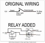
attachment.php

Yes as you can see. In this case the Inductance of the relay coil changes the circuit from a predominantly Resistive type to an inductive type and an inductive transient will occur and needs to be suppressed.

However, Normally the current draw from those low wattage bulbs is a non-issue.--Thank you RANDY
 
Last edited:

steveg

Yoda
Gold
Country flag
Offline
attachment.php

Yes as you can see. In this case the Inductance of the relay coil changes the circuit from a predominantly Resistive type to an inductive type and an inductive transient will occur and needs to be suppressed.

However, Normally the current draw from those low wattage bulbs is a non-issue.--Thank you RANDY

OK, so if I understand correctly, a capacitor wouldn't be necessary because the bulbs heat up slowly (in electronic terms) and so wouldn't cause a spark to jump across the switch points anyway. The author was using the relay 10 years ago because the pressure switches available were too light-duty and couldn't hold up to the bulbs' 3 amps for any length of time. Not sure why the relay by itself wouldn't be sufficient.

He doesn't explain exactly what the diode was for.

So maybe the switch quality has been rectified in the meantime and the new ones will last for an acceptable length of time.
If not, there's still an argument for the pedal-switch alternative.
 

Keoke

Great Pumpkin
Country flag
Offline
He doesn't explain exactly what the diode was for.

The addition of the diode tends to reduce the amplitude of the inductive transient produced by the relay coil.

However, most of the time the diode is not used in low voltage circuits.
 
OP
AUSMHLY

AUSMHLY

Obi Wan
Country flag
Offline
And why was the original hydraulic switch deleted? My BN6 is still energizing its brake lights with a something '58 date-coded switch, and problem-free.

You're a lucky guy Randy, 1958 brake switch still working.
For the rest of us, when our original brake switch stop working, we replace them with what's offered, aftermarket repros.

Reproduction parts aren't usually made as well as original, so they seem to fail even quicker. Don't get me started. I went through 2 reproduction switches. When it was time for the 3rd switch, I read on this forum that another option was the mechanical (do-dad) ones. The Watson worked great for years, then the other day, someone told me, you know your brake lights aren't working. What!? So I opened the switch to find out why and wanted to give a heads up to those who also have this switch.
 
Last edited:

90dog

Member
Country flag
Offline
Sorry to resurrect an older thread, but here goes:

The quite-possibly-original brake light switch on my '67 BJ8 has quit. I've ordered a Intermotor replacement, but having read several posts on the subject I'm not confident of its longevity. After reading Steve's great posts (and pics) of his snap-action switch mod, I've ordered one of those as well, just to hedge my bets.

Then I came across the relay mod idea. I always thought relays were for higher draw items, but I'm game if it's a good idea. My question is whether the consensus these days is that it's better to go mechanical, or roll the dice with the aftermarket replacement for the OEM?

Thanks!
 

Warren

Freshman Member
Country flag
Offline
I am on my 2nd Watson's. The first one lasted about a dozen years. It was replaced with another in 2020. The original hydraulic was kept in place and reconnected until a replacement arrived. Problem is detecting a brake light failure in time to avoid a situation.
Mine fortunately failed in the "on" position and was discovered quickly. I've gotten in the habit of "pre flight inspections" before most drives.

WD 67 BJ8
 
Similar threads
Thread starter Title Forum Replies Date
R TR6 Limit Mechanical Advance on TR6 distributor? Triumph 8
S TR2/3/3A Mechanical buddies. Triumph 2
Magyar Rebuild Speedometer & Tachometer - mechanical or electronic? Spridgets 17
A BN1 Mechanical Brake Switch Austin Healey 23
B TR4/4A Mechanical fuel pump vs electric Triumph 16
Healey Nut Mechanical tach drive Austin Healey 2
Healey Nut Mechanical tach drive assembly Austin Healey 4
K TR4/4A Mechanical fuel pump glass bowl level? Triumph 1
M Mechanical fuel pump Spridgets 33
M BE Mechanical Fuel Pump - Almost Certain Leak Spridgets 3
D TR2/3/3A Mechanical Fuel pump Triumph 3
steveg Checking Healey Mechanical Tach at idle Austin Healey 3
max71 MGB Here's what the inside of a MGB mechanical gauge looks like MG 0
tmcarthur Mechanical Fuel Pump Spridgets 9
J Mechanical tachometer to electric Austin Healey 11
DanLewis How far is your mechanical fan from the rear of your radiator? Spridgets 39
F Spitfire Spitfire 1500 Mechanical Fuel Pump & Spacer Triumph 6
P Bugeye Wiper Mechanical Parts needed Spridgets 1
DanLewis Distance between mechanical fan and radiator core Spridgets 17
T TR6 TR6 fuel line / mechanical fuel pump compression? Triumph 5
T Bypassing the mechanical fuel pump Triumph 8
regularman What was wrong with the 1500 mechanical fuel pump? Spridgets 20
Got_All_4 TR6 Moss TR6 mechanical fuel pump TR6 Triumph 25
T Mechanical tach options? Spridgets 17
B Mechanical & body service parts manual BJ7/BJ8 Austin Healey 2
S Mechanical Tach Repair and calibration Austin Healey 5
T More on mechanical fuel pumps Triumph 32
glemon stupid human tricks mechanical advance Triumph 25
bigjones The 1500 mechanical fuel pump Spridgets 21
S Mechanical Tach Problem Debugging Austin Healey 2
pjsmetana Electric Fuel Pump or carry a spare Mechanical? Triumph 15
pjsmetana Mechanical Sunpro Oil/Water Temp Gauge Triumph 5
RedTR3 TR2/3/3A TR3 Fuel Pump: Mechanical vs. Electric Triumph 14
TR6oldtimer TR6 TR6 Distributor mechanical advance question Triumph 4
veale001 Mechanical or Electric Fuel pump? Triumph 15
prb51 TR2/3/3A TR3 Op temp issue and mechanical gauge Triumph 7
philman Mechanical Oil Pressure Gauge Question???? Restoration & Tools 2
emann BE Mechanical Fuel Pump Installation Spridgets 0
E Body Blasting and Mechanical Work Triumph 9
7 springs for a lucas mechanical advance Triumph 1
Atrus Dizzy – Mechanical Advance Weights Spridgets 19
W Mechanical Fuel Pump Rebuild Spridgets 1
S Electric Fuel Pump vs. Mechanical Pump Triumph 18
Michael Oritt Guages--mechanical versus electrical Racing 31
drooartz Mechanical fuel pump with later 1275 Spridgets 2
V Website about most any auto mechanical question Triumph 1
B Mechanical Fuel Pump Spridgets 3
WALTER mechanical fuel pumps Spridgets 12
MGTF1250Dave TR2/3/3A TR3 or 4 Mechanical Fuel Pump Blanking Plate Triumph 4
T Electric vs Mechanical fuel pump? Triumph 3

Similar threads

Top