
Offline
I'm hooking up my Voltmeter in my Neg. grd BJ8 and want to know if anyone has a Wiring diagram they can post or PM me?
thanks
thanks

 Hey Guest!
Yep, I looked it up on a Hot Rod forum. I'm good. Thanks!Patrick--
Usually volt meters have only two contacts (not counting lighting). One goes to a positive source switched by the key and the other goes to a ground.
Its a Smiths Gauge. Lighting Wiring was done to red/white as original. Black ground as original. I'm undecided as to a green wire going to the switched fuse panel or a white wire from the ignition switch. When I craw under the dash tomorrow I'll make up my mind. Console and trans out right now so I have a Board across the floorboard with comfy cushions which should make the job easier. Clock hooked up yesterday with a green/red wire. I want to think out connection of clock because I want it to run with the battery switch turned off. Heater Boost switch now provides manual electric fan operation, but I still have a parallel circuit for thermostatic control of the engine fan. (I have Austin AC system).If you have a voltmeter (not an ammeter) you shouldn't require a proper wiring diagram for hooking up the gauge.
If it's a Smiths gauge, either gauge terminal can be connected to chassis ground (preferably with a black wire), the other terminal connected via a green wire to any green wire you find behind the dash. If the gauge is a brand other than Smiths, the GND gauge terminal (perhaps a black wire) goes to chassis ground. As before, the remaining gauge terminal gets connected to any existing green wire behind the dash. Fuses are optional. If you want one, put it inline with the wire going to the car's green wire. Use something small, like 3 Amps.
Illumination can be one of two colors, red or red/white. Look for existing illumination bulbs behind the dash and splice your voltmeter's lamp wire into one of those wires.
Green wires are switched, fused wires in Lucas schemes. Connecting your voltmeter to a green wire means it will only be powered up when the ignition key is in the run position.
If you really meant ammeter, that wiring is totally different.
Patrick,
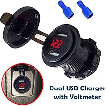
After my recent Dynamator alternator negative ground conversion I wanted to monitor charge, but I also wanted USB device charging capability so this little device was discreetly installed. It's sufficiently accurate too. Dynamator charges (13.8V) at around 800RPM and puts out 12.8V at idele 550 - 600. GONZO.
Clock hooked up yesterday with a green/red wire. I want to think out connection of clock because I want it to run with the battery switch turned off.
The brown wire is hot all the time unless the battery switch is off so I ruled that out. I'm thinking of running a wire to the battery as dklawson suggested. I don't want a wire unprotected or looking strange so I thought about a house thermostat type of wire, or similar, that has one or two wires in a vinyl sleeve. The clock doesn't use very much power so I'm not worried about using 16 ga wire. It'll run underneath the chassis and be secured to the battery cable with tie straps.The easiest way would be to run a wire from the clock to the "always hot" side of the cutoff switch.
OR:Alternatively
A Brown wire under the dash.
I wonder if that could be modified/adapted to just slip into the cigarette lighter...?Patrick,
After my recent Dynamator alternator negative ground conversion I wanted to monitor charge, but I also wanted USB device charging capability so this little device was discreetly installed. It's sufficiently accurate too. Dynamator charges (13.8V) at around 800RPM and puts out 12.8V at idele 550 - 600. GONZO.
I found a good website for the wiring diagrams for a Smiths Voltmeter, Ammeter & general Smiths gauges. Not a very good website when it comes to looking up things. I believe installation with the recommended 3 Amp fuses is important and I added a fuse holder in my Clock and Voltmeter gauges. I also used a Label machine and made a label strip/name for the wire as well as the fuse holder, "3 Amp". The first time I hooked up the Voltmeter I connected the hot wire to a terminal and because it was up high under the dash I couldn't see the other spade terminal and I assumed it was grounded by the case since the light worked. Well, I trouble shot it and found the other spade terminal. Works like a charm but I have to say the Voltmeter gauge doesn't make any fast movements...it's slow getting up to the voltage and you'd think it was not working unless you watched it for a while.The brown wire is hot all the time unless the battery switch is off so I ruled that out. I'm thinking of running a wire to the battery as dklawson suggested. I don't want a wire unprotected or looking strange so I thought about a house thermostat type of wire, or similar, that has one or two wires in a vinyl sleeve. The clock doesn't use very much power so I'm not worried about using 16 ga wire. It'll run underneath the chassis and be secured to the battery cable with tie straps.
I wonder if that could be modified/adapted to just slip into the cigarette lighter...?
it sure what that Gauge is. Can you post a photo?I like my Smith's "Battery Condition" voltmeter available reconditioned from sources in GB for around $120, but can understand why one would want one of the above for around $10 -- even if you had to wait a couple of weeks for the slow 747 from China.


