• Hi Guest!
    You can help ensure that British Car Forum (BCF) continues to provide a great place to engage in the British car hobby! If you find BCF a beneficial community, please consider supporting our efforts with a subscription.

    There are some perks with a member upgrade!
    **Upgrade Now**
    (PS: Subscribers don't see this gawd-aweful banner
Tips
Tips

General Tech Valve Timing--No Marks

KVH

Darth Vader
Silver
Country flag
Offline
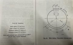
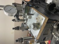
Taking back up on this fine old topic, and seeing some of what Mike (Popeye) and others have said, here's my issue. I followed both the Yakov Youtube video and a few good articles. I have TDC right on the mark. I also "degreed" the camshaft using Yakov's #1 cylinder intake valve lift methodology, and I set the maximum fully open point at which the crankshaft was set to 110 degrees after TDC (using the specs in the Triumph Shop Manual).

Yakov says I'm done and that I can fix the chain and move on, but I'm puzzled why I can't verify any of the other timing data shown in the Shop Manual. For example, shouldn't I be able to rotate the crank and see valve cam action corresponding to shop manual specs?

Also, I’m wondering about the two crank strokes, compression and exhaust. If I had the intake for Piston #1 at its highest point and set the crank to the correct corresponding degree (110 ATDC), and then verified that measurement with a dial gauge, with averaging, I assume everything must be right and that I could not have been on the wrong stroke.

I’m actually off by 2.5 degrees, and I understand if I flip the cam sprocket I might eliminate that—though it might be trial and error, as it might get 2 degrees worse.

Anyway, I guess I’m just looking for some guidance on the difference between the compression and exhaust strokes, and why it seems there are confusing statements made. I note that in the Youtube video, which really is great, I believe Yakov says he first started with the crank on the compression stroke and then rotated the crank to bring intake valve tappet #1 to its highest point, fully open. I assume when he did that he was then on the exhaust stroke. I say that because the other extremely detailed article on this makes a big point of being on the exhaust stroke for the adjustments. See Engine Rebuild (nonlintec.com)

Finally, is there a simple test that I have everything right—the head is off and I’m nowhere near complete with the engine. In the article, it is stated:

"I measured the crank positions for a specific intake and exhaust tappet height above the minimum (I used 25 mils). Because of slack in the chain, these points must be approached while turning the crank and camshaft clockwise, the normal direction of the engine. If the chain is adjusted right, these points will be equally spaced either side of TDC; the actual value is not important. I measured precisely 7 degrees for both, so I was confident that the chain was installed correctly and the timing was right."

I guess by “above the minimum” he means you rotate the crank until the tappets are at their lowest point, then proceed from there.

Oh, well, I guess that’s it for now. Happy Thanksgiving everyone!
 
2-1/2 degrees is not bad for a street engine. If it is advanced, it moves the torque band to a slightly lower RPM. If it is retarded, then it moves the torque to a higher RPM. Plus, as the chain wears the timing will slowly retard, so advanced 2-1/2 degrees is a good start. I haven't watched the videos, so I cannot respond to them, but if your spec is 110 degrees for max lift, and you have that set, then you are good.

If you have any doubts, leave the front cover off until the heads are on and you can run a compression check. But that shouldn't be necessary.
 
Do you have the workshop manual ?
It's so much simpler...
 
I did the same, top dead center and degreeing a new cam, mostly based on Rusty Beauties YouTube. The motor wasn’t stock, so I wasn’t looking at any marks. I had to do it twice to double check because I thought maybe my degree wheel moved - it did. Maybe that led to my trouble, but when done and put back together, it wouldn’t fire. Apparently I had the compression and exhaust strokes mixed up. I forget which vice versa now, and it was confusing then. I figured it out with a good illustration or animated video showing the compression and exhaust strokes, and then matched that understanding with how the cam had been degreed and what valve was ready to open. Then it was clear that my distributor shaft was off 180 degrees. Fired up immediately after the 180 degree flip of the distributor shaft and rotor.

Unless I moved the whole kit and kaboodle a full rotation, and I sure tried not to get far away from where everything was when I found TDC with the rotor at #1at the beginning of the adventure, but possible, it seemed like it should work putting it back together with the rotor at #1, but it didn’t.

Not sure If that’s any help.

Steve
 
That was helpful, but I have an important question.

Are you saying that everything worked because you turned the distributor around 180°?

Or are you saying that you had to go through two steps – – turn the distribute around 180° and remove the front timing cover and reset the relationship between the cam sprocket and the crankshaft?

If just the distributor, I’m happy. I made that mistake twice and it’s fixable in 15 to 20 minutes. The other would be a bigger problem and an ego buster.

Thanks again and I look forward to your response.
 
Here's what I did:


Any method that is based on things like the point where the valves open or finding TDC by watching a micrometer is likely to be inaccurate, because those points are not easy to determine precisely that way. I'm also not thrilled with the shop-manual procedure, for much the same reason.
 
Yes Steve I read your material and followed that as best I could. I think I’m done finally. I wish I better understood the theory behind the two engine strokes and the cam lobe opening/closing periods. I note for example that full open is one half the cycle, and that makes sense, but I don’t recall reading anything in the manual pointing out such a basic fact.
 
What Steve mentions is correct, and also why reading cam specs can be frustrating. Each manufacturer chooses an arbitrary amount of opening to use in their duration specs. The opening is started slow, and then picks up the pace. Likewise, the valve movement as the lift maxes out also moves slowly.

The best place to measure lift is some number near the middle of the lift curve. You have to measure on the lift side, and then match the same number on the closing side...and then average the 2 to find the most precise cam timing.

This same issue applies to finding the piston top dead center. There is little motion at the top, so it is best to measure 2 points and average them...one going up, and then one going down.
 
And I did find TDC with a piston stop and a point before and after with the degree wheel and some simple math. I’m thinking that maybe when I did that a second time after my degree wheel moved, maybe I put a rotation on the engine.

I will say, without YouTube I don’t think I would have imagined replacing the camshaft with just a shop manual. One needs a certain level of understanding I’m not sure I have to confidently follow just a written manual, though the Triumph publications are good and seem to be written for an average bloke.
 
Here’s a question I think is worth asking. The shop manual shows a drawing of the intake and exhaust cam lobes in “balance.“ The explanation given is that one valve is just beginning to open and the other is closing. This “point of balance” Is used as a reference when the distributor is set at TDC of the compression stroke. It is clear from the discussion in the shop manual that the two cam lobes in question are numbers seven and eight.

My question is whether having the cam lobes of a particular piston in balance has reference to any other important aspect of tuning, other than for cam lobes seven and eight of piston number four at TDC of the compression stroke? For example, are the cam lobes of piston number one in balance at TDC of the exhaust stroke?
 
When intake valve # 7 is just beginning to open and exhaust valve #8 is closing that's known as 'on the rock' or "point of balance"
Piston # 4 is ending it's exhaust upstroke and beginning it's down intake stoke
At the same time piston #1 is at the TDC of it's compression stroke and both valves 1 and 2 will be firmly closed
And in those conditions is when a cam like the stock TR cam is timed...either straight up or slightly advance up to 4 degrees.
 
When intake valve # 7 is just beginning to open and exhaust valve #8 is just about closed that's known as 'on the rock' or "point of balance"....
Piston # 4 is ending it's exhaust upstroke and beginning it's down intake stroke... overlap
At the same time piston #1 is at the TDC of it's compression stroke and both valves 1 and 2 will be firmly closed
And in those conditions is when a cam like the stock TR cam is usually timed...either straight up or slightly advance up to 4 degrees.
 
The valves are "balanced" at TDC when opposite the firing stroke for each cylinder. In other words...#4 cylinder is balanced TDC when #1 is firing. #2 would be balanced when #3 is firing, and vice versa.
 
The valves are "balanced" at TDC when opposite the firing stroke for each cylinder. In other words...#4 cylinder is balanced TDC when #1 is firing. #2 would be balanced when #3 is firing, and vice versa.
Interesting. thx
 
I'm about done obsessing about my cam settings, but before I mark my sprockets I just want to raise a final point. Please see the Specs below from the Shop Manual. I have no idea how to use those Specs to double check anything. I followed the Youtube (Yakov) and much of what I found in other posts, and I'm certain I've got the cam within a degree of Spec, but what is that drawing and Spec list talking about?

First off, to which valves are the Specs referring? 1 and 2, or 7 and 8? The entire discussion on the same page was about reaching balance between valves 7 and 8 to find TDC on the compression stroke, so I assume those are the valves. But I could still make no sense of the Specs. There is no procedure I was able to follow that would, for example, show me that the Exhaust Valve "opens" at 57 degrees BBDC. Rotating the crank and watching my pushrod "replacements" simply would not allow verification. The numbers were way off and made no sense--or more likely I didn't know what I was doing.

Also, does the Shop Manual mean fully open? Just beginning to open? There is, of course, a "dead" spot on each cam lobe where the tappets simply don't move--I forget how many degrees. And maybe I'd need a degree wheel on the camshaft as well to make sense of the Specs.

Since I followed the published procedures and have the #1 Intake valve peaked at 110 degrees ATDC I feel that I'm done, but I wish I understood the Shop Manual specs better, and how to verify them.

An education would be appreciated. Thanks all.
 

Attachments

  • Cam Spec 2.jpg
    Cam Spec 2.jpg
    60.1 KB · Views: 86
  • Cam Degree Process.jpg
    Cam Degree Process.jpg
    116.1 KB · Views: 85
Not for this car. Never had them. But I do feel I’m set correctly. It’s my understanding that is lacking.
 
The diagram is for all the cylinders. It is just giving you the specs on the cam, to reference if you choose to install a different cam. It shows both the intake and exhaust valve position in relation to crank rotation over the 720 degrees of a full cycle.

The manual specs are really unusable, as they do not tell you what lift is considered "opening" or "closing". Competition Cams states that their lift measurements are based on .050" off base. So for CC you can measure .050" lift and that will match the cam specs. On our cams we do not know if they are using .001", .020", or .050". This is also why some cams sound really radical, but it is really only because they were taking their measurements from .002" off base, while the other cam measures .050" off base. This measurement difference makes a huge difference in spec duration.

I would assume the dead spot is the base of the cam, where the valve is closed and there is no motion of the lifter.

Modern cam manufacturers are much easier to understand, as they give you the points they consider opening and closing. Trying to find those points on a cam that does not specify the lift that is considered opening or closing will have you chasing your tail. The lift is SO SLOW at the opening and closing points that you will have a range of numbers instead of a specific number.
 
That makes perfect sense, and, yes, I’ve been chasing my tail. I find ways to do that in various aspects of life. It’s a habit that can be quite frustrating, though in the end it usually serves me well because I learn something in the process, even about myself. Thanks for clarifying that for me. I’m gonna put this thing together and drive it soon.

My engine has been hanging on the engine stand now for more than two years. I hope those grade 8 bolts don’t experience fatigue, because I’ll be putting the head on soon and don’t want my toes crushed.
 
Back
Top