-
 Hi Guest!
You can help ensure that British Car Forum (BCF) continues to provide a great place to engage in the British car hobby! If you find BCF a beneficial community, please consider supporting our efforts with a subscription.
There are some perks with a member upgrade!**Upgrade Now**
(PS: Subscribers don't see this gawd-aweful banner

Tips
- We have a special forum called "Member Articles" where you can submit actual articles for consideration for publication. Learn More
- Don't have an Avatar? If not, your avatar will default to the 1st character in your username. Go into "Account Details" to change your Avatar.
- Some basic forum navigation info: click
 Hey - did you know if you click on the title of a thread it will take you to the first unread post since you last visited that thread?
- Hey Guest - Is your British Car Club in our Clubs database? If not, send me a PM - Basil

- Looking for a local club? Click the "Clubs" tab above and browse hundreds of clubs world-wide.
- Add Android or iPhone APP: click
- Did you know - any picture or video you add in your posts in any marque-specific forum will also get added to the Media Gallery automatically.
- A few more tips about posting and replying: click
- Hey there Guest - be sure to keep your profile page up to date with interesting info about yourself: learn more
- More tips and tricks on Posting and Replying: click
 but were afraid to ask:
  STOP!! Never post your email address in open forums. Bots can "harvest" your email! If you must share your email use a Private Message or use the
  smilie in place of the real @
- Want to mention another member in a post & get their attention? WATCH THIS

- So, you created a "Group" here at BCF and would like to invite other members to join? Watch this!
- Hey Guest - A post a day keeps Basil from visiting you in the small hours and putting a bat up your nightdress!
- Hey Guest - do you know of an upcoming British car event?
 Pretty Please - add it to our Events forum(s) and add to the calendar! >> Here's How <<
- Hey Guest - you be stylin' Change the look and feel of the forum to fit your taste. Check it out
- If you run across an inappropriate post, for example a post that breaks our rules or looks like it might be spam, you can report the post to the moderators: Learn More
- If you would like to try some different "looks" or styles for the site, scroll to the very bottom, on the left and click the Style Selector.
You are using an out of date browser. It may not display this or other websites correctly.
You should upgrade or use an alternative browser.
You should upgrade or use an alternative browser.
Two totally lame gearbox wiring questions
- Thread starter tdskip
- Start date


trrdster2000
Luke Skywalker
Offline
Skip, new ones will work just fine, you will just need to change to a spade connector.
Wayne
Wayne
bgbassplyr
Darth Vader
Offline
Don't think either are reverse sensors. One should be for 3rd gear OD, the other for 4th.
TR3driver
Great Pumpkin - R.I.P
Offline
Yes, from a 3A before 1960. Yes, later switch will work fine, just add suitable terminals to the wire.tdskip said:1) This very early crash box (possible from a TR3A even) has a different style connector that the later cars. Can it be replaced with a later sensor?
<div class="ubbcode-block"><div class="ubbcode-header">Quote:]2) One this gearbox there are two sensors, is the front one or the back one the reverse sensor?[/QUOTE]Neither one, they are both for the OD. One will close when in either 3rd or 4th; the other closes when in 2nd. Switches are wired in parallel, so OD is available in 2nd, 3rd or 4th.
Note that the book talks about the washers under the switch being important to 'time' the OD engagement. Not sure how important it actually is, but why take a chance?


TonyPanchot
Jedi Trainee
Offline
Where is the switch location for the reverse lamps ?
When I had my trans swapped I lost the use of the reverse
and was told there was no place to make the connection
When I had my trans swapped I lost the use of the reverse
and was told there was no place to make the connection
TR3driver
Great Pumpkin - R.I.P
Offline
It depends, it was in different locations for different years; and some simply did not have a place for it. In Geo's photo above, you can see the blank spot where the reverse switch would be, if that cover were drilled & tapped for a reverse switch. But some later covers had it on top near the shift lever, and some had it on the LH side.TonyPanchot said:Where is the switch location for the reverse lamps ?
You can see some of the variations at
https://www.zeni.net/trf/TR6bluebook/82.php
Don Elliott
Obi Wan
Offline
There is no switch for the back-up lights on the TR3A because there are no back-up lights.
TR3driver
Great Pumpkin - R.I.P
Offline
A "reversing lamp" was listed as a factory option (tho not a very popular one it seems, and possibly deleted from later option lists. And TR2-early TR3 did have the reverse switch hole drilled, tapped and capped with a brass plug.Don Elliott said:There is no switch for the back-up lights on the TR3A because there are no back-up lights.
Hi guys - one more totally lame wiring question.
When wiring together the switches does it matter which terminal I string together with the yellow wiring? Or, does it only matter that current can flow through them - thus making it unimportant which terminals are connected provided there is a good ground and "up stream" connections?
Where did you connect your grounds from the ground too? Just a local ground hear the transmission or on the transmission itself?
Thanks!
TR3driver
Great Pumpkin - R.I.P
Offline
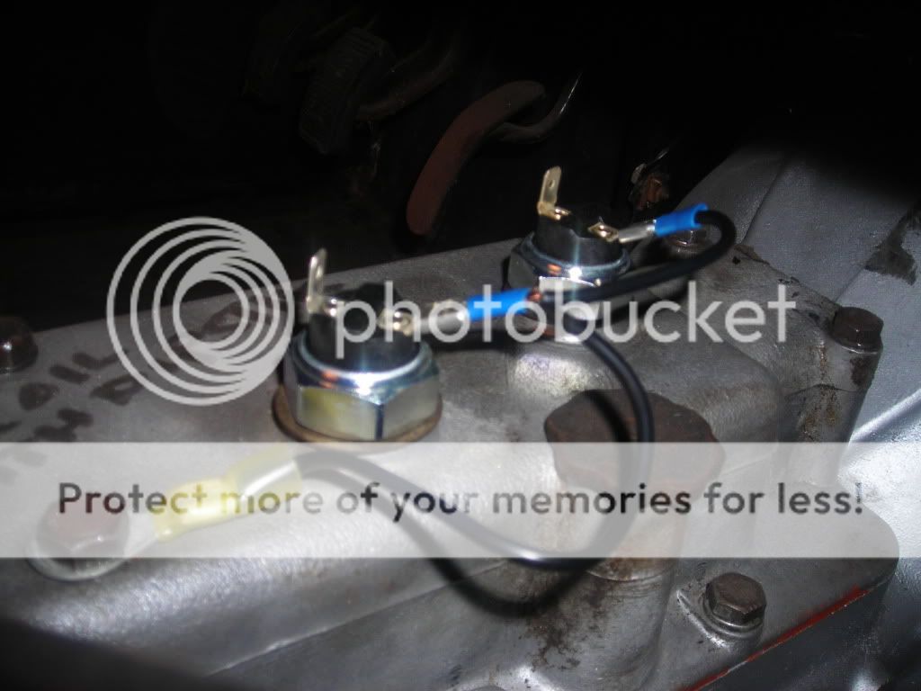
Doesn't matter which terminal is which. The book says to use one of the top cover bolts for the ground, but it doesn't really matter. If you look at my photo above, you can see where the harness is tie-wrapped to the ring terminal I used for the ground.
Don't forget that the two switches are wired in parallel, meaning you need two ground wires (one for each switch).
Don't forget that the two switches are wired in parallel, meaning you need two ground wires (one for each switch).
TR3driver said:Don't forget that the two switches are wired in parallel, meaning you need two ground wires (one for each switch).
The wiring diagrams appear to show the grounds connected between the switches, and then a ground to transmission or body coming from the second switch? Randall, are you saying each switch should have a separate ground?
Thanks!
TR3driver
Great Pumpkin - R.I.P
Offline
Sorry for the confusion, Tom. Either way will work fine; the ground for one switch can either be daisy-chained to the other switch (as the book shows) or wired directly to ground.tdskip said:The wiring diagrams appear to show the grounds connected between the switches, and then a ground to transmission or body coming from the second switch? Randall, are you saying each switch should have a separate ground?