• Hey there Guest!
    If you enjoy BCF and find our forum a useful resource, if you appreciate not having ads pop up all over the place and you want to ensure we can stay online - Please consider supporting with an "optional" low-cost annual subscription.
    **Upgrade Now**
    (PS: Subscribers don't see this UGLY banner)
Tips
Tips

Tri-carb PCV valve

  • Thread starter Deleted member 21878
  • Start date

John Turney

Yoda
Silver
Country flag
Offline
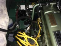
i have been looking at the air inlet issue and have modified my plumbing to what i think gives me an air intake without changing the looks... too much.

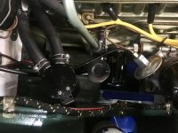
first, at the side cover, i took off the hose elbow and replaced it with a "T". i plugged the old vent pipe that goes up to the valve cover. (acutally at both ends) this makes that old vent pipe there just for looks really. back to the "T", the one leg goes to the side cover, the middle one is plugged to old vent pipe, and the other end comes up and goes to my catch can. From there of course it goes thru the PCV and on to the manifold port.

since the valve cover "T" is now plugged on the vent pipe side, the other side is left open and connected back to the back of the air breather. (stock look) this should now be sucking air in and gets some filtering there. i also rolled up some foam filter material and put it in the hose for a little extra filtering.

with this setup i should be pulling air from the breather, thru the valve cover, thru the engine and on to the oil catch can.

i was concerned about how much air i would pull thru this hose. (5/8" opening) might be too much to keep a vacuum in the oil pan or control air to the PCV. So i restricted the opening in the hole to 1/8" with a fitting in the hose. Not sure why i chose that size. just figured it was a place to start and i had the fitting. i can adjust that smaller or larger.

good thing is, if i do not like it, i can change it back by just pulling the rubber plugs and putting the rubber elbow back at the side cover.

i also thought about just putting a rear side cover in the middle for another hose connection. probably a cleaner look (too many hose clamps at that lower "T") but the side covers are way too expensive, if you can find a rear one.
View attachment 57716View attachment 57717
i need to reposition the catch can to get the pipe as straight as possible. i have some options there. and then, of course, i need to test.
I tried something similar and found my oil catch tank filled with oil quickly, so test carefully.
 
OP
D

Deleted member 21878

Guest
Guest
Offline
Ray,
you are only now wondering???? ha, you should talk to my wife.

yes, my primary objective was to help stop oil leaks or potential ones down the road. everything i am changing is just what you said earlier, "an experiment".

i got time... and i am curious. i do not expect to get it to work like modern cars. i don't even think they use PCV valves anymore. But car makers went to PCV systems with a fresh air intake in the mid-sixties. must have been a reason to change after only a few years. From what i read it was to help with situations of excess vapors and/or positive crankcase pressure. Maybe from high RPM, heavy load, worn engine parts...

My thinking, or concern, is that maybe my first plumbing setup may create too much vacuum. i believe you mentioned one possible problem in that it may promote more blow-by. it also has no way to release possible positive crankcase pressure should that occur. (and i have no way to test that it won't occur) Then, if most air is getting sucked in the rear main seal at a high rate..., how much clutch dust is it pulling in with it?

in other words are we close to a balance with the right amount of vacuum in the Nock system? is the PCV valve even controlling the air flow? is it the valve or the available air? that could explain why some people have success with this system and some don't. Maybe some have more blow-by or other places for air intrusion such as older worn seals.

So since it is winter and i got time to play, i thought i would check out other options. My inlet could very well let in too much air. if so i think i will be able to tell pretty quick. i can then make the hole smaller or even plug it totally quite easily.

Looking back at old Triumph systems from the early TR6's, they just put a "T" off the PCV valve with one side going to the valve cover and the other going to the air breather. How much vacuum could they be pulling in the engine with that? And how did they not have a vacuum leak condition? Should we all be using the valve Dean suggested above?

Sorry for being so long, i got on a roll.

John
you know...as i finished up today, i thought about where i was pulling the vacuum from.... Close to where a lot of oil is sloshing, dripping. i knew i could not be the first person who had thought of this.
guessing why you see most vac lines coming from a valve cover to the PCV valve? Less oil at the top. So that is a concern. And i think you confirmed that concern. i may need to rethink this.

Did i mention i got time? haha.
 
Country flag
Online
"... i don't even think they use PCV valves anymore ..."

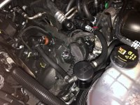
They do ('19 5.0 Coyote engine with aftermarket catchcan installed; the PCV valve is the orange/brown plastic on the left):

PCV.JPG

PCV valves are effective at reducing pollution--and simple and cheap--but are problematic in that crankcase goop is introduced into the intake manifold. Doubly problematic with Gas Direct Injection engines.

When I installed Nock's PCV 'system' in my BJ8 my oil consumption was cut in half (as was the spot on the garage floor). I assumed, since the PCV valve was vented to the 'spare' vacuum boss at the back of the manifold, that the back 3 cylinders and ports would be gunked-up. On teardown, there was no significant difference with the front three (the worst cylinder, compression-wise, was #2). I was going to have my engine builder--a very meticulous and accomplished Kiwi--install a rear main seal; he insisted I stick with the PCV setup instead and rigged a better solution.
 
Last edited:
OP
D

Deleted member 21878

Guest
Guest
Offline
Bob
i stand corrected. i thought car makers today had gone to a restrictor as opposed to a valve. guess some have and some have not. thanks for the info.
 

RAC68

Darth Vader
Offline
Drone-Dog,

You make some good points and, most import, is our inability to know the amount of vacuum to satisfy stopping leaks without causing unintended consiquence. As I understood the PCV is our vacuum-governing component and would close if the amount of vacuum exceed that which it has been designed to do and close. Since each engine is different, PCVs are not interchangable and, as you have mentioned, do not publish the valve's max operating vacuum.

Since we don't even know the general run-rate operating vacuum inside the engine, I must assume that sometime in the past, someone has done some research to select the PCV we are using and it was a selection based upon something more then that the end tubes fit nicely in our tube and/or manifold fixture. Based upon this assumption, I would then see the restricted vent you have installed to be less important. However, if my assumption is not valid, your addition is quite important as excess vacuum will not only pull additional oil and contaminants but could increase cylinder blow-by or even pull lubricant from the rear main and possibly leaving it less protected.


Bob indicated that, when dismantling his engine for rebuild, he found little difference between the PCV ported side and its counterpart. Additionally, he indicated that his trusted engine rebuilder suggested he stay with the PCV rather than change to a rear main seal. Assuming Bob is using the same PVC as we, I would suggest the PCV will manage vacuum properly for our engine and your restricted outside port may not be needed. I stated may-not rather then will-not as, although his rebuilder favored his PCV installation over a oil seal, Bob's positive experience was with a warn engine (as mine) and we will need to wait for Bob to share his results on his tighter rebuilt engine (as yours).

This spring I will install the PCV and document, as best as I can, my results. Hopefully, as we both share our experimental changes, we can come up with more definitive approach will address the necessity for a PCV that will be good for all.

Just my thoughts,
Ray(64BJ8P1)
 
OP
D

Deleted member 21878

Guest
Guest
Offline
"our inability to know the amount of vacuum to satisfy stopping leaks without causing unintended consiquence."

exactly!

even engines within the same make are different. In this case Bob's engine does not have the rear seal kit and mine does. i am also running gapless rings and all brand new seals. i would think that would create more vacuum in my block... well unless the PCV is compensating for that. Hard to know.

the thing that got me to thinking about this was my first test run. i wanted to check to see if i had any connections leaking. i checked the dipstick since i had tried to make a seal for it. i pushed down on it hard enough to make sure it sealed and held it a few moments. i heard this pop, consistent with the sound of the oil pan getting sucked in. after i shut the car off, i heard another pop as if the oil pan popped back out. i was surprised there was that much vacuum.

it may mean nothing. i just don't know. That is when i began to wonder if my valve was controlling the vaccum/volume or the amount of air that could get in. i would think it should be the valve for the most part. And eventially came around to thinking about trying to introduce some fresh air.

the next time i started the car and ran it, i did not mess with the dipstick and never heard the pop. So must be pulling some air around the stick.


Country flag
Online
"... we will need to wait for Bob to share his results on his tighter rebuilt engine ..."

I've got about 6K miles on this engine with no issues; hopefully, I never have to tear it down again.

I think the thing to remember is that the 'Nock Solution' isn't a true PCV system, as there is no fresh air source. I think the PCV valve pulls a mild vacuum when the engine's at idle--the most vacuum except for hard deceleration--and little to none at WOT (so it would behave more-or-less like the breather vented to an air intake). Keeping some vacuum on the engine reduces oil sneaking by the scroll 'seal' at the rear of the crank but otherwise it doesn't do much. I think it would take a pretty significant vacuum to suck air past the rings, given they have to retain pressure many times greater. I believe crankcase pressurization robs some engine power, so a slight vacuum might be beneficial.

I've heard less oil consumption should be seen on long, non-stop runs, as the oil tends to get past the scroll when the engine stops. That has been my experience.

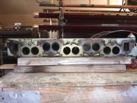
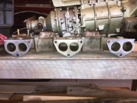
Here's shots of the head and manifold at the teardown:

Cyl Head.jpg

manifold2.JPG
 
Last edited:

RAC68

Darth Vader
Offline
Hi All,

Bob:
I must agree with your contention that blow-by may not be increased with increased vacuum from the PCV. As I understand, the specifications built into a PCV make it specific to a engine. However, I would suspect that more then one engine would have simiar (close enough to fall within the margin of manufacer error) specifications and use the same PCV.
Also, I don't rememember seeing a PCV air source on the earlier cars models that Nock would have made his valve selection from.

Drone-Dog:
Wow! If you are retaining enough vacuum in your engine to cause even slight deformation of any component, I agree, it is too much vacuum. Although I don't anticipate having the same issue, I think I will be experimenting with not sealing the oil cap and dip stick and then sealing it to see if there is a difference. The air going into the engine will not be filtered but then neither is the air being pulled through the rear main or the air cleaners (other than rocks and stones).

Great fun,
Ray(64BJ8P1)
 
Last edited:
OP
D

Deleted member 21878

Guest
Guest
Offline
Bob
first of all i am happy your system works so well. hey your story is main reason i started this.

i am not sure i understand the blow by. the rings are designed for lots of compression pressure. (agreed) but the vacuum and pressure are not independent. So you are adding pressure which they probably weren't designed for. Now having said that, i am reading that crankcase vacuum actually sucks the rings out to the cylinder walls which reduces blow by. that is probably why people see a reduction in oil usage.

the thing i can't quite get my head around is what the PCV valve is controlling. all i can get is that it is just there to control the air to the manifold to control a vac leak condition at different rpm's. it does not control any vacuum in the crankcase.

the question is how much vacuum is good. from what i am reading on some tech articles you only want a "slight" vacuum in the crankcase. too much causes seal leakage in reverse pulling in dirt, etc. it also will pull oil mist out of the air which helps to oil parts and cylinder walls.

So how much is "slight"? in two articles i read it should be 4-6 inches of H2O. yes H2O... conversion to HG would be about .4-.5 HG. that isn't much.

when i did my vacuum tests above i did them on the back side of the PCV which told me nothing other than the vacuum the intake would pull. obviously enough. what i need to do is test the vacuum in the crankcase. i am going to see if i can make up a piece to attach my vac gauge to my dipstick tube. then measure vacuum there. that will give me the balance of vacuum being pulled vs blow by pressure, etc.

Ray, that seemed a lot. plus when i pull off my oil cap you can definitely hear and feel the vaccum. does not seem quite right to me. but atmospheric vacuum is powerful so it does not take a lot to be noticable. i may be closer than what i think to being good. hopefully the test above will tell me.
 
Country flag
Online
Drone Dog,

I installed a PCV valve in order to decrease oil getting past the rear seal, and on the underside of the car and my garage floor. I assumed a rear main seal kit would solve that problem--I bought it years before my latest engine overhaul--but my mechanic recommended against it. Does your seal not stop, or at least significantly reduce your oil leakage? I've heard the seal's effectiveness is 'hit or miss.' We installed one on our BN2's engine and it both leaks and has excessive crankcase pressure; I wish there was an easy way to install a PCV valve on that engine.
 

RAC68

Darth Vader
Offline
Drone-Dog,

I can see where the crankcase breather you installed would perform whether restricted or not. Lets assume that you are starting with a positive pressure in your crankcase. The application of vacuum to the internal-engine would reduce this pressure and pull air through your breather. If air is pulled through your breather, a small negative pressure would also be applied to the main rear and would likely assist the reverse screw in keeping oil in the engine. However, when the PCV is closed and air is not being pulled into the engine, any additional pressure in the engine above ambient atmospheric would be vented to the outside so pressure will not rise above atmospheric. Since pressure is not above ambient, oil loss through the rear main is not assisted and the reverse screw may be sufficient to maintain oil within the system. If oil is still lost (reverse screw not performing as designed), then and only then would I look to placing a restriction on your breather in order to increase a negative pressure environment within the crankcase.

Conclusion, with your breather and PCV, you should never have pressure buildup above ambient and therefore reduce the possibility of oil being pushed and lost through the rear main.

My thoughts,
Ray(64BJ8P1)
 
OP
D

Deleted member 21878

Guest
Guest
Offline
Bob
i do get some oil out of the seal kit. not sure if it reduced or not since i added it when i rebuilt the engine. i bought the car in boxes so had never had any experience with the engine before hand.

Ray
i did some tests today and will post in the next thread.
 
OP
D

Deleted member 21878

Guest
Guest
Offline
Today i ran some tests to see how much pressure my PCV system might create in the crankcase. here is what i think.. hope it does not get too long. if it does, i apologize.

first off i changed my plumbing back to my first setup. John brought up a good point of maybe i was drawing the vacuum at the wrong place and could pull out too much oil. so in all of these tests the vacuum is being drawn from the valve cover. the only difference this time is i left the left side of the metal "T" on the valve cover plugged. So i was only pulling air thru the valve cover.

start up:
i put a hose on the side cover with a 1/4" fitting on it and a cap on the fitting so there was no vacuum leak.
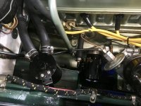
fullsizeoutput_2d4.jpg
i started the car to let it warm up. the info i had said the vacuum in the crankcase should be measured with the engine hot and at idle. while it was warming up, i pulled the oil filler cap. that is quite a large hole but the engine idle never changed. this leads me to believe that the PCV valve we are using is probably well suited for my car. Since i am now under the impression the valve is only there to control air volume to the intake. So far so good.

first test:
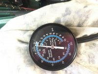
i next hooked my vac gauge to the fitting you see in the pic above. keep in mind the vent pipe is plugged at the "T" so it is not pulling air. at idle and engine warmed up, i was pulling 5-6 in/HG. from what i have read i feel like this is too much vacuum. and i am not sure my dipstick is even sealed well. but i thought this would be a good base line. So this is where i started.

2nd test:
i capped the hose barb again and hooked my gauge to the dipstick tube. this was an issue as soon as i slid the hose over the tube sealing it. vacuum started climbing rapidly. FYI: at 9 in/HG the oil pan pops. it was at 10 and still climbing before i could get the rubber cap off the hose barb on the side vent. as soon as i pulled it off, the vac dropped below 1in/HG. i tired a few different pieces i could insert in the hose barb but i either got less than one inch vac or over 3 in/HG.

i know the articles i read said the vac at idle in the crankcase should be basically .4-.5 in/HG. But i am not sure how well i can measure that with my gauge. Which is why they probably measure it in in/H2O. just not enough distance between the marks to feel good with that. So i set my goal to get the vacuum in the 1-2 range hoping to get it as close to 1 as possible. i tried a number of different orifaces. shoving fittings of different sizes in hoses and checking the gauge. the 1/8" hose barb fitting i had would give me 2.5 in/HG (the hole size is actually about 5/64) and the 3/16 tubing i had would give me less than 1. so i figured i had to be somewhere in between.

third test:
the problem with the way i was tesing is it did not take in to account what might leak thru the dipstick. going with a suggestion here earlier, i changed my seal to include an oring at the bottom of my current seal. then put the dipstick back in. at the side cover, i installed a "T" again. on top of the "T" i connected my vac gauge and on the end of the "T", i put my oriface.

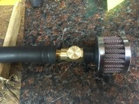
since i had not achived the number i wanted, i took the smaller 1/8" hose barb and drill a 9/64" hole thru it to make it a little bigger and hopefully get a reading closer to my goal. i also installed the barb in an air filter to make it as close to the final layout as possible. just in case it had some effect.
IMG_0771.jpg
the hose you see in the pic coming up is going to the vac guage.

the new oriface gave me a reading of 1 in/HG. i pushed on the dipstick and held it to see if it made a difference and it did not. So i think i got the dipstick sealed decently. Oring did the trick.

while i had this hookup set, i tried changing engine speeds. idle, 1000 rpm, 2000 rpm, accel and decel. none of those changes made any difference in the vac reading. Another reason i think the PCV valve is probably a good choice. it must be compensating well for the change in manifold vacuum.

Conclusion:
So this is the way i am going to leave it... well as far as hook up anyway. i may change some hose lengths to get this a little better aligned. and i might change where the filter is sitting. i don't think the filter really needs to be that big. if i can get a smaller one, i might move it behind the brace so it is not so noticeable.

if i have the engine at idle now and pull the oil filler cap, i get a little vac noise but not near as much as before. So i am getting what i think is closer to the proper vacuum. and unless i find out something different, i think i am getting enough vacuum. there is also lots of info about the benefits of getting fresh air in to an engine. this is long enough so won't list here.

other than cleaning it up a little, i want to keep an eye on the oil catch can for a while to see how much oil it pulls in. i think with reducing the cranckcase vacuum it should not draw out as much oil. the only issue may be the oil slinging from the rocker assembly right below the "T". a baffle under the valve cover would greatly help that.

Thats it. All i got.
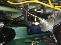
fullsizeoutput_2d6.jpgIMG_0772.jpg
last setup and gauge reading.
 
OP
D

Deleted member 21878

Guest
Guest
Offline
Steve,
thanks. i did not have any pictures and i could not remember if it had one or not. makes sense that it would.
 

RAC68

Darth Vader
Offline
Drone-Dog,

We now have information on this subject that is definitive and not just hypothetical. I must admit I am quite surprised in the amount of vacuum being pulled and the extent of pressure reduction achieved, even with your initial vent oriface. Based upon the high vacuum achieved initioally, I am wondering if you took initial reading and determine the original level of crankcase pressure buildup with the original Healey piping setup. The original setup was meant to relieve internal pressure buildup and allow the reverse screw rear main to stop oil from leaking. If higher then ambient pressure is preset, then the original setup is not sufficient and would further emphasize the appropriateness of your redesign.

DD, Great Job,
Ray(64BJ8P1))
 
Last edited:
OP
D

Deleted member 21878

Guest
Guest
Offline
Ray
i did not take any readings before hand. it would have been interesting. but i would assume it would have been all positive pressure. i think the plan of the day was to have a pipe big enough to handle the flow they expected from blow by.

i am not so sure how much others can take from my results. but i do think it is worth others, using this system, to check.

As we said before, all these cars are different. one thing that did amaze me was how little a change in the oriface size changed the amount of vacuum. Tells me it does not take much of an air leak, say at the dipstick or the oil filler cap, to change results. For that matter with my enigne having about 1000 miles on it, i wonder if the results on it will not change as it wears in.

I was thinking about that today and thus made a couple of changes while i was moving the filter. the first change was to move the one plug to the top of the side vent pipe from the "T" in the side cover. with this set up, i only have to loosen that one hose clamp, pull the pipe, remove the rubber plug and hook up my vac gauge to check the vac at any time. in fact i added it to my list of winter checks for each year.

second, as i was walking thru HF this morning gettting some brushes, i noticed a little in-line air control valve on the wall. hey 4 bucks, so figured i would give it a try. i think they use these valve to control air to paint guns. anyway, the opening in it was bigger than what i drill for my oriface. this gave me the idea to remove my fixed oriface and insert this in the line. then i could dial in my crankcase pressure to account for any changes that may happen.

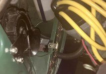
And as i said earlier i moved the filter so that it is not as noticeable. i made a little bracket and attached it under a wire harness P clip. holds the filter solid and it is out of the way.

So at this point, i just want to start the car again and dial in the pressure to about 1 in/hg again.

IMG_0774.jpgfullsizeoutput_2d8.jpgfullsizeoutput_2da.jpg
 
Country flag
Online
Update: I just checked the catch can on my Mustang Coyote (5.0L V8) and was kind of surprised--shocked, actually--to find almost a teaspoon of oil in it after only a few hundred miles of driving. Yeah, the port injection part of the dual-injection system should keep the intake valves clean, but that won't prevent gunk buildup on the intake manifold and throttle body. I really can't understand why most, if not all, engines don't have a catch can, unless it's cost and owners can't be trusted to check and empty them (it could be done at normal maintenance inspection cycles).
 

steveg

Yoda
Gold
Country flag
Offline
Having reinstalled the PCV, with my Air Fuel Ratio and Exhaust Gas Temp gauges, can report it had no visible effect on either AF ratio or EG temp.

The DMD manifold balance pipe setup makes it possible to draw the vacuum from both carbs equally.

screenshot.1625.jpg
 
Similar threads
Thread starter Title Forum Replies Date
B PCV Valve Tri Carb Austin Healey 11
Zitch SOLD!! SOLD - Tri-Carb Exhaust manifold for a 3000 Austin Healey Classifieds 0
T Air Filter Recommendations for My Tri-Carb Austin Healey 7
HealeyPassion For Sale Tri-Carb Complete Set including manifolds Austin Healey Classifieds 13
Healey Nut Tri-Carb Throttle Controls Austin Healey 4
D Tri carb: order of installation question. Austin Healey 5
Healey Nut Tri-Carb Project Austin Healey 213
CLB62 1962 BT7 Tri-Carb for sale on BaT Austin Healey 2
D 62 tri-carb upper fulcrum pins Austin Healey 4
M engine stutter of rebuild BT7 engine [tri-carb] above 2500 rpm Austin Healey 27
lbcspinners 1962 Austin-Healey 3000 Mk II BN7 Tri-Carb 2-Seat Roadster: for sale on BaT Austin Healey 2
D Grose valves / Tri-carb Austin Healey 11
D 62 tri-carb fuel line connection Austin Healey 10
C Tri carb Austin Healey 7
T Tri-carb questions. Austin Healey 10
J BT7 [Tri-Carb] Restoration Upgrades Austin Healey 2
D 62 tri-carb tuning question Austin Healey 8
D BT7 Tri-Carb Distributor Cap Austin Healey 9
D BT7 tri-carb linkage set up Austin Healey 23
D BT-7 tri-carb Two more questions Austin Healey 18
D BT-7 tri-carb ring gap Austin Healey 10
D BT7 tri-carb installing my crank Austin Healey 4
D 62 / BT7 tri-carb engine Austin Healey 16
D 62 tri-carb wiring harness Austin Healey 10
HealeyPassion Tri-carb intake manifold balance tube size Austin Healey 10
steveg Rare colored tri-carb BT7 on eBay Austin Healey 13
davidb AH 3000 tri-carb throttle shafts Austin Healey 13
W Barrett Jackson Auction 62 2 Seater Tri-carb only brings 48k Austin Healey 19
Norman Tri carb - overheating issue ???? Austin Healey 10
K Tri-carb help Austin Healey 11
K Tri-carb help please Austin Healey 0
AH67 62 MKII Tri Carb, done with some pictures Austin Healey 9
M WTB: Tri Carb Choke Linkage Parts Austin Healey 8
BoyRacer What are MK II [tri-carb] 2 seaters selling for? Austin Healey 12
D BT7 Tri carb Backfire Austin Healey 2
M Tri Carb Camshaft Austin Healey 4
B tri carb problems Austin Healey 17
B Gas mileage Tri-Carb Austin Healey 2
A tri carb on ebay Austin Healey 14
C Cold air box for Tri Carb 3000 BT7 ??? Austin Healey 9
G tri carb vapor lock Austin Healey 30
J Seeking tri carb help Austin Healey 16
M 100-6/ 3000 tri carb set up Austin Healey 13
Patrick67BJ8 Ruddspeed Tri-Carb Set-up Austin Healey 9
6 BN7 tri-carb will not start Austin Healey 7
6 BJ8-BT7 Tri-carb Conversion? Austin Healey 7
C Tri - Carb assistance ! Austin Healey 5
Dave Richards WOW! a "RARE" tri-carb Austin Healey 12
C AH 3000 Tri-Carb conversion. Austin Healey 4
V Choke cables for tri-carb Austin Healey 5

Similar threads

Top