• Hi Guest!
    You can help ensure that British Car Forum (BCF) continues to provide a great place to engage in the British car hobby! If you find BCF a beneficial community, please consider supporting our efforts with a subscription.

    There are some perks with a member upgrade!
    **Upgrade Now**
    (PS: Subscribers don't see this gawd-aweful banner
Tips
Tips

Tracing Lucas wiring [tips?]

beebopbogo

Member
Offline
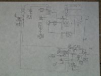
I was getting so frustrated this past week! I couldn't make heads or tails of the wiring diagram in the back of the Haynes manual. But then I started copying over the diagram onto a separate piece of paper by hand. Boy am I learning a lot! I think I've reached one level closer to Nirvana, too! /ubbthreads/images/graemlins/smile.gif

Anyway, my problem is that quite a few of my guages aren't working. Temp, fuel, tach guages are no go, as well as the wiper motors. If you look at my diagram I made in the attachment above, you'll see that power comes from the battery/alternator to fuse #4 in the fuse box (brown wire), to the ignition swith, back to the #3 fuse in the fuse box, then through all the things that don't work that I've already mentioned. In other words:

+--wipers--#3fuse--IGN--#4fuse--BAT(positive)
|
+--VoltageStabalizer--fuel--temp--Ground(negative)
|
+--tach--Ground(negative)

But here's the thing: Using my multimeter I see that all the brown wires (between BAT and IGNITION) have 12.5V while all the wires for my faulty equipment only have .05V with the ignition key turned on (0.0V with ignition off).

Alright, I know what you're thinking. "This is all way too complicated for me to help." I guess that's probably true, but if you have any leads on what a common cause of guages to go out would be, please reply.

PS I realize how bad the quality is of my graphic. At least it gives a vague idea of what I'm up to...
 

Attachments

  • 89391-IMG_1093.JPG
    89391-IMG_1093.JPG
    112.4 KB · Views: 189
First things first. Relax...crack a cold one. Feel better? K. check the fuses and the fuse block itself (these are notorious for being a PITA. clean and tighten ALL grounds. visually inspect harness for for damage. odds are you have a bad ground. Check your switches.

Do you have 12 volts coming off the ignition switch going to all things inoperable? Perhaps the swith has failed? the way i understand your post is you have 12 volts to ignition switch but not leaving the switch. is this correct?

Mark
 
I have two switches, I think, both located on the right hand side of the hood compartment, attached to the fender (little black cylindrical things with 4 connectors on the bottom).

1) One has Brown, two White wires (same connector), Black, and White/Brown connected to the bottom.
With ignition off, only brown has power (12V)
With ignition on, brown has 12V and the two whites have 12V

2) The second switch has two Browns (same connector), two White/Reds (same connector), a White/Brown, and a Black.
With ignition off, only the browns have power (12V)
With ignition on, nothing changes. ie, only browns have power.

I think the 1st switch is the Ignition Switch Relay and the 2nd switch is the Starter Solonoid Relay, by reference to the Haynes wiring diagram.

Got to go to work now, but I'll check the grounds when I get back.
 
Ignition Relay Switch for sale, anyone?

Yaaaaahhhh!!! I found the problem! The Ignition Relay Switch (the black cylinder attached to the inside of the right fender) was bad. Instead of using that to get power to my guages, I tried hopping over directly with a spare piece of wire. My windshield wipers immediately started to wipe! woohoo!

The moral of the story: Redraw the important parts of the electrical diagram. It was my understanding of which wires go where that gave me the final clue.

Anybody have a parts car? The ignition relay switch is $21 from Moss...
 
Re: Ignition Relay Switch for sale, anyone?

not that hard. is it?
Congrats~!~


mark
 
RE:

Only two weeks of work... Not too hard at all (pff).

I took the relays apart, learned how they work (quite simple idea, really), cleaned them, put them back together, tested them, and now they work. And as with Lucas, this simply led me to another problem. I'm not sure if it's related or not, but let me describe the problem:

I turn the ignition to ON. The starter immediately activates until I switch the ignition back to OFF. The problem is that power is being sent to the starter even though the ignition isn't turned to the spring-loaded start position.

My current hypothesis is that the ignition switch has a problem and is sending power to the white/red wire when it's not supposed to. Power then goes to the 3rd fuse in the fuse box, on to the solonoid relay, and finally to the starter. I figured since cleaning the relays worked so well, I'll rebuild the ignition switch. I'll post my results within the next few days...
 
Re: RE:

beebopbogo
Take that wiring diagram down to Kinko’s and use their blue print copier to enlarge it to about 30 inches wide. I had mine laminated and it now hangs on one wall of the garage. Great for problems, just use a grease pen to trace the circuit. As for parts, you should get to know Chris Roop. He has both new and used parts and will give you a discount off of Moss prices on new orders. The benefit to you is that he is a nice guy and is located in Oregon.
https://www.oregontrail.net/~roopsmg/index.htm
 
Back
Top