• Hi Guest!
    You can help ensure that British Car Forum (BCF) continues to provide a great place to engage in the British car hobby! If you find BCF a beneficial community, please consider supporting our efforts with a subscription.

    There are some perks with a member upgrade!
    **Upgrade Now**
    (PS: Subscribers don't see this gawd-aweful banner
Tips
Tips

TR6 TR6 Aluminum Valve Cover Gasket

TR6Dan

Member
Country flag
Offline
Hello all,

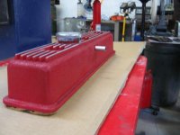
I'm sure this has been asked multiple times. I am replacing my stock valve cover with a polished aluminum one. I plan to make an aluminum baffle and JB Weld it in to help prevent oil from ending up in the carbs. What valve cover gasket would you suggest? Most of the posts I have seen have suggested a silicone gasket; is this the only option or can a cork gasket be used? With either gasket should it be installed dry or should it installed using some kind of sealant or adhesive? My car does not have an egr valve so at least I don't have to deal with that being in the way.

Thanks,
Dan
 
Hi Dan,

I went for the silicone gasket from Gasket Innovations (originally Justin Wagner now I believe it's TSI?) on my Triumphtune
Cover. I applied the gasket to the bottom of the cover with some gasket adhesive.

Not sure about the cork gasket being available for aftermarket covers.

Cheers
Tush
 
The following is my generic, general technique on valve covers regardless of aluminum or pressed steel, cork gasket or silicone.

  1. Clean the top of the cylinder head and mating surface of the valve cover. Remove all old gasket debris, old sealant, oil, and grease.
  2. Now smear the top of the head with a thin film of axle grease.
  3. With clean hands, press the new gasket down into that thin film of grease on the top of the head. Press the gasket down flat all the way around.
  4. Apply a thin bead of RTV to the valve cover where the gasket will sit.
  5. Fit the valve cover to the head making sure the gasket seats where it needs to on the valve cover.
  6. Install the cover securing hardware... FINGER TIGHT and no more.
  7. Allow about 6 hours for the RTV to cure.
  8. After 6 hours, tighten the valve cover to its normal torque.

If you follow this method then the bottom surface of the gasket will conform perfectly to the head. The RTV will fill any voids between the top of the gasket and the valve cover with almost no force applied. In short, this method compensates for surfaces that are not flat or parallel and even gaskets that are not uniform.
 
Dan,

I use the same basic approach as dklawson with a stock cork valve cover gasket.

As far as the baffle goes, I ran into a similar problem with an older version of the TriumphTune valve cover. I then complicated things by going to roller rockers which the deep set bosses for the hold down studs would not clear. Attached are pictures, one showing the baffle from the inside of valve cover, one showing the rivet heads on the outside of the valve cover and the third showing valve cover with the stock cork gasket peeking out from the underside.

The baffle was made form .020" 5052-O (IIRC, might have been 3003 and gage might have been .016 or .025, it was just something we had sitting around) aluminum sheet stock that was formed with the top end attached with JB Weld and the larger lower flange attached using two AN470A-3-16 button head solid rivets and JB Weld. Those are a 3/32" rivet made from 1100-O aluminum that is 1" long. The 1" rivets cost less than any of the shorter sizes and we just cut them to the grip length we need with enough excess to properly make the formed head. The baffle is a little narrower than I wanted but the clearance with the roller rockers is tight enough that it was made as wide as I dared make it.

The other problem mentioned above was that the mounting bosses on the old style TriumphTune valve covers were recessed and they fouled the roller rockers. Since I was too cheap to buy a new later style cover and was looking for "a challenge," I made a drill template from a piece of steel plate that was machined to fit the inside contours of the valve cover with the then existing mounting holes as the guide. Then the cover was put on a milling machine and the bosses milled away from inside the valve cover. Plugs were made from some 6061 aluminum plate stock we had sitting around and welded in. Back on to the milling machine to machine them to be almost flush, then drilled using the drill template made earlier. Hit it with some wrinkle red and then used a couple of different ScotchBrite Roloc discs, a somewhat fine to knock the paint off the ribs and then extra fine to finish them up.
 

Attachments

  • IMG_0306.jpg
    IMG_0306.jpg
    20.8 KB · Views: 152
  • IMG_0307C&C.JPG
    IMG_0307C&C.JPG
    20.1 KB · Views: 152
  • IMG_0308.jpg
    IMG_0308.jpg
    43.7 KB · Views: 140
Back
Top