
-
 Hey Guest!
British Car Forum has been supporting enthusiasts for over 25 years by providing a great place to share our love for British cars. You can support our efforts by upgrading your membership for less than the dues of most car clubs. There are some perks with a member upgrade!**Upgrade Now**
(PS: Upgraded members don't see this banner, nor will you see the Google ads that appear on the site.)

Tips
- We have a special forum called "Member Articles" where you can submit actual articles for consideration for publication. Learn More
- Don't have an Avatar? If not, your avatar will default to the 1st character in your username. Go into "Account Details" to change your Avatar.
- Some basic forum navigation info: click
 Hey - did you know if you click on the title of a thread it will take you to the first unread post since you last visited that thread?
- Hey Guest - Is your British Car Club in our Clubs database? If not, send me a PM - Basil

- Looking for a local club? Click the "Clubs" tab above and browse hundreds of clubs world-wide.
- Add Android or iPhone APP: click
- Did you know - any picture or video you add in your posts in any marque-specific forum will also get added to the Media Gallery automatically.
- A few more tips about posting and replying: click
- Hey there Guest - be sure to keep your profile page up to date with interesting info about yourself: learn more
- More tips and tricks on Posting and Replying: click
 but were afraid to ask:
  STOP!! Never post your email address in open forums. Bots can "harvest" your email! If you must share your email use a Private Message or use the
  smilie in place of the real @
- Want to mention another member in a post & get their attention? WATCH THIS

- So, you created a "Group" here at BCF and would like to invite other members to join? Watch this!
- Hey Guest - A post a day keeps Basil from visiting you in the small hours and putting a bat up your nightdress!
- Hey Guest - do you know of an upcoming British car event?
 Pretty Please - add it to our Events forum(s) and add to the calendar! >> Here's How <<
- Hey Guest - you be stylin' Change the look and feel of the forum to fit your taste. Check it out
- If you run across an inappropriate post, for example a post that breaks our rules or looks like it might be spam, you can report the post to the moderators: Learn More
- If you would like to try some different "looks" or styles for the site, scroll to the very bottom, on the left and click the Style Selector.
You are using an out of date browser. It may not display this or other websites correctly.
You should upgrade or use an alternative browser.
You should upgrade or use an alternative browser.
TR4/4A TR4 Overdrive Switches--Top Cover
- Thread starter KVH
- Start date

Geo Hahn
Yoda
Offline
JerryVV said:Follow the wiring diagrahm. There is not a positive and negative at each switch. You are only controling a ground to the relay via the top cover switches.
That daisy chain of switches:

I added an indicator light:

I also added a diode to prolong relay life per you-can-guess-who's suggestion:

This is the diode I used:
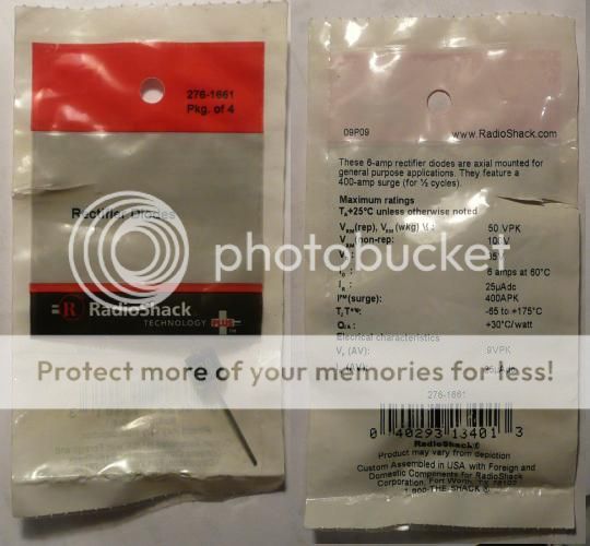
Note -- these images are for POSITIVE GROUND. The diode in particular would have to be reversed for negative ground.
OP
Offline
I don't have any mechanics or engineers in the family. I'm it, and I owe a lot to everyone on this Forum.
I need to find a good article about auto electrics. I'd enjoy reading it.
So, what do those OD Cover switches do when you drag the shifter from 4th to 3rd? Or over to 1st or 2nd?
How do they correlate to the workings of the solenoid?
What's happening when you're in neutral?
I need to find a good article about auto electrics. I'd enjoy reading it.
So, what do those OD Cover switches do when you drag the shifter from 4th to 3rd? Or over to 1st or 2nd?
How do they correlate to the workings of the solenoid?
What's happening when you're in neutral?

Offline
Geo Hahn said:I also added a diode to prolong relay life per you-can-guess-who's suggestion:
What is the purpose of the diode?
TR3driver
Great Pumpkin - R.I.P
Offline
When you go through neutral, both switch plungers drop down, so both switches are open and the solenoid is disengaged. There is a sentence in some manual (perhaps the A-type service manual, don't recall offhand) that talks about the timing of that event being important relative to the synchro operation, which is why you are supposed to shim the switches. (The shafts have a ramp where the switch plungers ride, so the height of the switch affects the timing of the switch closure relative to the motion of the shaft.)
My original OD relay on TS39781LO lasted a long, long time; but I was having trouble with replacements becoming erratic within a year or so of installation (including a fairly expensive reproduction relay). So I added a diode to act as a snubber, to hopefully keep the kickback voltage from the solenoid from causing an arc at the relay contacts as they open. The result seems to have worked out very well, even with a cheap relay (under $3 in bulk).
I just grabbed a diode from the parts bin, but I believe it was rated for around 1 amp and 50 volts. Anyway, I think any diode with those ratings (or higher) would work fine. The one Geo shows above would work, or here's another example:
https://www.radioshack.com/product/index.jsp?productId=2036270