• Hey Guest!
    British Car Forum has been supporting enthusiasts for over 25 years by providing a great place to share our love for British cars. You can support our efforts by upgrading your membership for less than the dues of most car clubs. There are some perks with a member upgrade!

    **Upgrade Now**
    (PS: Upgraded members don't see this banner, nor will you see the Google ads that appear on the site.)
Tips
Tips

TR2/3/3A TR3A Transmission

RonR

Jedi Trainee
Country flag
Offline
Folks,

During my unsuccessful TR3A drive to VTR, the transmission stopped shifting into first and second gears. Yesterday I removed the top cover from the transmission to investigate. After some time of moving things back and forth, the linkage started working. The problem seems to be that the anti-rattle plunger had managed to slip out and jammed the first/second shifter rod. The spring remained in-place. Is there anything unique to this installation? I am planning on buying a new spring and plunger.

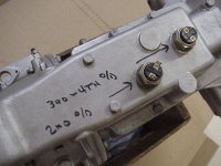
Also, for some reason, this transmission has 2 isolator switches on the top with the forward (first) switch wired as a switch and the second one wired simply as a connector. I would insert a photogrpah but that skill seems to be beyond my ability.

Thanks.
Ron
 
You might want to examine the slots where the end of the shift lever rides, and the end of the shift lever for damage. Normally the slot is narrow enough to hold the plunger well into the hole in the shift lever, so unless the plunger came out in pieces, I suspect something else is worn/damaged.

The isolator switches are supposed to be wired in parallel, so the OD works in 2nd, 3rd & 4th. The forward switch closes in 3rd & 4th, while the rear one closes in 2nd. Here's a photo, courtesy Geo Hahn:
 

Attachments

  • 26273.jpg
    26273.jpg
    56 KB · Views: 524
Thanks Randall.

I will inspect the shifter lever and the selector rod ends for wear.

The photo is exactly like the switches on my trnasmission. The "power" wire from the OD switch goes to the 3rd/4th switch, a wire conencts the two switches, and the final wire goes from the 2nd OD switch to the solenoid. For some reason, my car does not have an OD relay and the OD works fine.
 
RonR said:
...For some reason, my car does not have an OD relay and the OD works fine.

I suppose it is possible to wire an OD w/o a relay by making the switch carry the full load... but since switches are about 50 bucks I think adding a relay might be prudent.
 
I ended up making my anti rattle thingy, got a drill bit and cut it and went to ace hardward and got a spring of suitable size and stiffness,,so far works good. will know more when I get the car back on the road and check out the new rebuilt transmission and OD

Hondo
 
Folks,

Not surprising, I need a little more help in correcting the wiring of the overdrive isolator switches. Figures 41 and 43 under the Gearbox section in the Service Instruction Manual illustrate the wiring. My post-detached-retina eyes are having a difficult time of figuring out what exactly is required, but I am sure my car is wired wrong as the ground wire is missing and only one wire is going to the rear switch.

From the illustrations, it appears that a wire from the dash switch is connected to one side of the “forward” (third/fourth gear) switch. The other side of this switch appears to go to ground. I cannot tell which sides of the forward switch feed which sides of the rear (second gear) switch. Nor can I tell which terminal on which switch feeds the overdrive solenoid.

Thanks in advance.
Ron
 
FWIW, Ron, my TR3A with factory OD was not wired quite the way shown in the book. It had the operating switch on the dash wired between the ignition switch and the relay coil; with the other side of the relay coil wired to the isolator switches. Doesn't really matter, just works out a bit simpler.

Here's a better diagram of the isolator wiring, from Dan Masters:
 

Attachments

  • 26294.jpg
    26294.jpg
    80 KB · Views: 414
PS, I also found that adding a diode across the solenoid greatly improved the life of the relay. The original relays were apparently tough enough to not need a diode, but both the reproduction I bought and two modern relays I tried after it gave up within a few months of installation. With the diode, I've been running the same cheap relay for many years now.

ODrelaywithdiode.jpg

(The diode is inside what appears to be a black wire, grounded by the same bolt that holds the relay.)
 
It seemed a bit counter-intuitive to me (also an ex-detached retina guy) because the switch is switching the ground on & off (as opposed to the more common arrangement of a switch operating power).

FWIW, here's a diagram showing where I added the aforementioned diode on my + earth TR:

OD%20Diode.JPG
 
Geo Hahn said:
It seemed a bit counter-intuitive to me (also an ex-detached retina guy) because the switch is switching the ground on & off (as opposed to the more common arrangement of a switch operating power).

I find it helps to visualize "ground" as simply being a wire back to the other battery terminal. The "ground" just happens to be made of steel and shaped like a car :laugh: Once you start looking at these things as complete circuits (rather than battery to magical ground), then it's perfectly reasonable to break the circuit anywhere to deny power to a device (like a relay coil).
 
does the diode come in different sizes or ratings? If so, what size should I bee looking for?
Does Radio Shack carry these or can you recommend a different source?

It appears from the wiring diagram you installed the diode from the C2 terminal of the relay to ground? Is this correct?

Thanks

Ron
 
RonR said:
does the diode come in different sizes or ratings? If so, what size should I bee looking for?
Does Radio Shack carry these or can you recommend a different source?

I got mine at Radio Shack:

ODDiode.jpg


RonR said:
It appears from the wiring diagram you installed the diode from the C2 terminal of the relay to ground? Is this correct?

Yes, but note that the 'direction' you will mount the diode will depend on whether you have positive or negative ground (the diagram I posted is for positive ground).
 
Pretty much any power or 'rectifier' diode will do, provided it is rated for 1 amp or more and 50 volts or more. Likely the one I used is rated 1 amp and 200 volts, but it's just what I found in the junk bin.

One end of the diode body will have a stripe (just barely visible at the bottom edge in Geo's photo above). For positive ground, the striped end gets connected to ground. If you run negative ground (as I do), it goes the other way.

The idea is to have it connected across the solenoid. It was just easier to install it at the relay; the wiring is equivalent.
 
Folks,

I have the overdrive relay and diode wired per Randall's and Geo's instructions.
On a 150 mile drive today the overdrive worked great for the first 30 miles or so. Then it would stop working but later begin working again, as if something got warm and needed to cool off.

Prior to installing the relay and diode, the overdrive had worked perfectly each time it was engaged regardless of the length of driving the car. It had been wired "direct" without the relay or diode.

Any thoughts?

Thanks
Ron
 
My suggestion would be to temporarily wire in a indicator light, to show when the solenoid is actually receiving power from the relay. Put it some place you can see while driving, and take another trip. If the light stops working too, then there is a problem with the relay and/or wiring. But if the light keeps working, the problem is with the solenoid or OD itself.

I've had similar problems both when the relay flaked out, and when the pull-in contacts in the solenoid were dirty/oily. Solenoid adjustment being right on the edge can cause problems like that, too.

Most recently my A-type went intermittant because (I think) chunks of the broken thrust washer were getting hung up in the non-return valve. But it was also shifting really slow, so that's probably not your problem.
 
Back
Top