• The Roadster Factory Recovery Fund - Friends, as you may have heard, The Roadster Factory, a respected British Car Parts business in PA, suffered a total loss in a fire on Christmas Day. Read about it, discuss or ask questions >> HERE. The Triumph Register of America is sponsoring a fund raiser to help TRF get back on their feet. If you can help, vist >> their GoFundMe page.
  • Hey there Guest!
    If you enjoy BCF and find our forum a useful resource, if you appreciate not having ads pop up all over the place and you want to ensure we can stay online - Please consider supporting with an "optional" low-cost annual subscription.
    **Upgrade Now**
    (PS: Subscribers don't see this UGLY banner)
Tips
Tips

TR2/3/3A TR3A Overdrive Wiring Harness Installation

Rob-Michigan

Freshman Member
Offline
Hello,

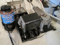
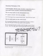
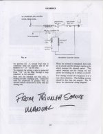
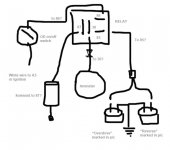
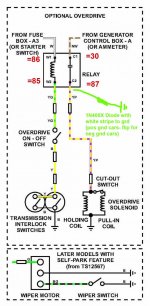
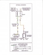
Last summer I bought a nice 1959 TR3a with a bad original gearbox. I ordered a reconditioned one with overdrive from an East Coast company. It promptly arrived and appears to have all I wanted, four speed synchro, OD and new replacement parts including clutch and related hardware. The fellow who sold it to me told me he also, as requested, installed it with a TR4 bell housing which apparently has a thicker flange to mount to the engine, better for more horsepower should I want it. This TR4 bell, he said, will require re-boring of the rear mounting bolt holes. It also had the switch, relay, solenoid for the OD with one wire attached and two wiring harnesses; an upper and a lower. With it was a sheet showing some information about how to wire the relay.

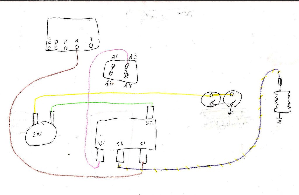
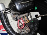
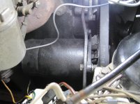
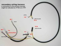
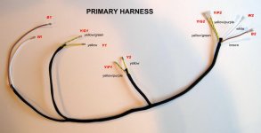
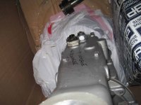
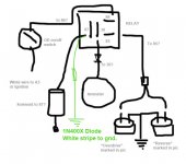
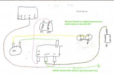
I’ve begun to remove the old transmission but before I do, I want to fully understand how to wire up the new one. My problem is that I don’t really know which wires go where. I have a couple of diagrams and I made photos of the harnesses. I have noted colors of the wires and need to know what goes where. I sent the photos to the fellow I bought it from but over the months I guess he has had some personal issues and I just can’t pin him down. I’d like to get the job done so if someone can help I would be very grateful. The vertical wing image with the colored wires (third from left) is one I found from a post here on the forum and, I think, holds the most promise. The car has no reverse lights and one of the harnesses may be from a TR6. I’ll attach the images.

Cheers,
Rob
 

Attachments

  • image03549.jpg
    image03549.jpg
    163.9 KB · Views: 263
  • image03550.jpg
    image03550.jpg
    169.4 KB · Views: 249
  • image03551.jpg
    image03551.jpg
    151.6 KB · Views: 762
  • secondary harness.jpg
    secondary harness.jpg
    189.4 KB · Views: 340
  • wire.jpg
    wire.jpg
    191.8 KB · Views: 317
Last edited:

TR3driver

Great Pumpkin - R.I.P
Offline
Neither one of those harnesses look right to me. One I recognize as being for a J-type OD, the other I don't recognize at all.

What wiring parts do you have already?

The factory apparently used several slightly different circuits. All are equivalent in function, but this diagram matches most closely the factory OD wiring on TS39781LO

The difference is that it has the operating switch (which for a LHD 59 TR3A would be on the dash to the left of the steering wheel) wired between the ignition switch and OD relay, instead of on the other side of the relay coil. It reduces the number of wires slightly. The change to the other configuration (with the operating switch between the relay & isolator switches) may have happened at TS60000, when all of the "Lucar" quick connects came in.

So, using that method, there is a white wire that runs from the "hot" side of the starter pushbutton (electrically equivalent to the ignition switch, but more convenient) to the operating switch. (You can also run it to A3 on the fuse block as the diagram says, but my car had it on the starter switch.) Then another wire runs from the operating switch down to the relay. On my car, that wire was in a piece of sleeving along with the wire from the starter pushbutton, so the wire ran back to the vicinity of the ignition switch and then through a second piece of sleeving down to the relay on the back of the battery box. (All of the wiring colors were faded to a uniform brown, so I can't comment on what colors the factory used.) Another wire ran from the ammeter, through the sleeve, to one of the relay contacts.

Then two wires run together from the relay, one to the isolator switches on top of the gearbox, the other to the solenoid on the OD. The two isolator switches are connected in parallel, one side of each switch to ground and the other side of each switch to the wire from the relay. Here's a photo I saved that more or less shows the gearbox setup:


The diagrams don't show any fuses, but I suggest adding an in-line fuse in the line from the ammeter to the relay contact. That way, if the solenoid gets jammed somehow, it will blow the fuse rather than burning up the solenoid. The solenoid actually has two windings inside, and a pair of contacts that open and reduce the current once the solenoid has moved completely. If a bit of gravel or whatever gets in there and blocks the motion, the "pull-in" coil will quickly overheat and burn out. Solenoids have gotten cheaper since then, but the fuse still seems like a good idea to me. I used a MDL-8 "slo-blo", but an ordinary AGC 10 (or even 5) should work fine.

PS, if you do have the thicker mounting flange (as you can see in my photo above), you'll also need to use longer studs at the back of the engine block, and longer bolts. You'll also need to do something creative with the clutch slave mounting. But, I'm pretty sure all TR4 had the same flange as the TR3 (certainly the earlier ones did), so that may not be a problem depending on what John actually sold you.
 

luke44

Jedi Warrior
Silver
Country flag
Offline
There are a few variations on the overdrive wiring depending on serial number, but in the end they all do the same thing - power source, solenoid, relay and a switch. The variations simply switch a different component.

I also believe you have the F type overdrive harness for the TR4 as sold by Moss. The TR3 one is much simpler and not available - I ended up making my own - it's only a few wires.

Here is the schematic I made to make it easier to follow:

11106829745_3803560604_b.jpg
 
OP
R

Rob-Michigan

Freshman Member
Offline
Neither one of those harnesses look right to me. One I recognize as being for a J-type OD, the other I don't recognize at all.

What wiring parts do you have already?

The factory apparently used several slightly different circuits. All are equivalent in function, but this diagram matches most closely the factory OD wiring on TS39781LO

The difference is that it has the operating switch (which for a LHD 59 TR3A would be on the dash to the left of the steering wheel) wired between the ignition switch and OD relay, instead of on the other side of the relay coil. It reduces the number of wires slightly. The change to the other configuration (with the operating switch between the relay & isolator switches) may have happened at TS60000, when all of the "Lucar" quick connects came in.

So, using that method, there is a white wire that runs from the "hot" side of the starter pushbutton (electrically equivalent to the ignition switch, but more convenient) to the operating switch. (You can also run it to A3 on the fuse block as the diagram says, but my car had it on the starter switch.) Then another wire runs from the operating switch down to the relay. On my car, that wire was in a piece of sleeving along with the wire from the starter pushbutton, so the wire ran back to the vicinity of the ignition switch and then through a second piece of sleeving down to the relay on the back of the battery box. (All of the wiring colors were faded to a uniform brown, so I can't comment on what colors the factory used.) Another wire ran from the ammeter, through the sleeve, to one of the relay contacts.

Then two wires run together from the relay, one to the isolator switches on top of the gearbox, the other to the solenoid on the OD. The two isolator switches are connected in parallel, one side of each switch to ground and the other side of each switch to the wire from the relay. Here's a photo I saved that more or less shows the gearbox setup:


The diagrams don't show any fuses, but I suggest adding an in-line fuse in the line from the ammeter to the relay contact. That way, if the solenoid gets jammed somehow, it will blow the fuse rather than burning up the solenoid. The solenoid actually has two windings inside, and a pair of contacts that open and reduce the current once the solenoid has moved completely. If a bit of gravel or whatever gets in there and blocks the motion, the "pull-in" coil will quickly overheat and burn out. Solenoids have gotten cheaper since then, but the fuse still seems like a good idea to me. I used a MDL-8 "slo-blo", but an ordinary AGC 10 (or even 5) should work fine.

PS, if you do have the thicker mounting flange (as you can see in my photo above), you'll also need to use longer studs at the back of the engine block, and longer bolts. You'll also need to do something creative with the clutch slave mounting. But, I'm pretty sure all TR4 had the same flange as the TR3 (certainly the earlier ones did), so that may not be a problem depending on what John actually sold you.

Randall,

Finally, I think I am understanding how to do this, thanks! The relay is my only stumbling block. All the drawings of the relay except John’s refer to W1/W2 and C1/C2, John’s relay drawing is numbered 87, 30, 86 and 85. There are instructions for his relay but they use different language than what other people have said and I don’t want to blow the whole thing up. More accurately, I want to make sure the wiring I do will cause the OD to drop out of OD when the car goes to neutral. I’ll draw a pic of what I think should be the wiring and post it along with a pic of the transmission. The transmission has two switches, one marked “Overdrive” and the other “Reverse”. I assume together they are the “isolator switches” and should be wired as shown in my drawing.

Which of the two drawings do you recognize as the “J Type OD” and what is that to? I spoke with John several times when he was too busy to tell me how to set up the wiring but one time he did say one of the packets of wiring was from a TR6 but was the same as the TR3 except for some extra wires for a backup light or something. He did say it is synchro in first and set up for OD in 3[SUP]rd[/SUP] and 4[SUP]th[/SUP].

Anyway, if you OK the drawing I did as workable, I’ll adapt the harness John sent me to work for this application… I’ll just cop off the extra wires.

Thanks a million, Now for Thanksgiving and Happy Turkey Day to you.
Rob
 

Attachments

  • image03551.jpg
    image03551.jpg
    151.6 KB · Views: 184
  • IMG_0915.jpg
    IMG_0915.jpg
    192.8 KB · Views: 199
  • IMG_0918.jpg
    IMG_0918.jpg
    186.2 KB · Views: 152
  • IMG_0919.jpg
    IMG_0919.jpg
    187.6 KB · Views: 179
  • image03549.jpg
    image03549.jpg
    163.9 KB · Views: 154
  • image03550.jpg
    image03550.jpg
    169.4 KB · Views: 170
  • secondary harness.jpg
    secondary harness.jpg
    189.4 KB · Views: 151
  • wire.jpg
    wire.jpg
    191.8 KB · Views: 150
  • What I think should e the wiring.jpg
    What I think should e the wiring.jpg
    66 KB · Views: 324
  • New OD.jpg
    New OD.jpg
    141.7 KB · Views: 174
OP
R

Rob-Michigan

Freshman Member
Offline
Thanks Luke. I think I have it right in my drawing I posted in reply to Randall. If you and Randall could check my drawing and especially the relay posts I would be very grateful. The relay itself has no markings and I want to be certain I get the wires right on it.

Thanks again,
Rob
 
OP
R

Rob-Michigan

Freshman Member
Offline
Neither one of those harnesses look right to me. One I recognize as being for a J-type OD, the other I don't recognize at all.

What wiring parts do you have already?

The factory apparently used several slightly different circuits. All are equivalent in function, but this diagram matches most closely the factory OD wiring on TS39781LO

The difference is that it has the operating switch (which for a LHD 59 TR3A would be on the dash to the left of the steering wheel) wired between the ignition switch and OD relay, instead of on the other side of the relay coil. It reduces the number of wires slightly. The change to the other configuration (with the operating switch between the relay & isolator switches) may have happened at TS60000, when all of the "Lucar" quick connects came in.

So, using that method, there is a white wire that runs from the "hot" side of the starter pushbutton (electrically equivalent to the ignition switch, but more convenient) to the operating switch. (You can also run it to A3 on the fuse block as the diagram says, but my car had it on the starter switch.) Then another wire runs from the operating switch down to the relay. On my car, that wire was in a piece of sleeving along with the wire from the starter pushbutton, so the wire ran back to the vicinity of the ignition switch and then through a second piece of sleeving down to the relay on the back of the battery box. (All of the wiring colors were faded to a uniform brown, so I can't comment on what colors the factory used.) Another wire ran from the ammeter, through the sleeve, to one of the relay contacts.

Then two wires run together from the relay, one to the isolator switches on top of the gearbox, the other to the solenoid on the OD. The two isolator switches are connected in parallel, one side of each switch to ground and the other side of each switch to the wire from the relay. Here's a photo I saved that more or less shows the gearbox setup:


The diagrams don't show any fuses, but I suggest adding an in-line fuse in the line from the ammeter to the relay contact. That way, if the solenoid gets jammed somehow, it will blow the fuse rather than burning up the solenoid. The solenoid actually has two windings inside, and a pair of contacts that open and reduce the current once the solenoid has moved completely. If a bit of gravel or whatever gets in there and blocks the motion, the "pull-in" coil will quickly overheat and burn out. Solenoids have gotten cheaper since then, but the fuse still seems like a good idea to me. I used a MDL-8 "slo-blo", but an ordinary AGC 10 (or even 5) should work fine.

PS, if you do have the thicker mounting flange (as you can see in my photo above), you'll also need to use longer studs at the back of the engine block, and longer bolts. You'll also need to do something creative with the clutch slave mounting. But, I'm pretty sure all TR4 had the same flange as the TR3 (certainly the earlier ones did), so that may not be a problem depending on what John actually sold you.

Randall,

Finally, I think I am understanding how to do this, thanks! The relay is my only stumbling block. All the drawings of the relay except John’s refer to W1/W2 and C1/C2, John’s relay drawing is numbered 87, 30, 86 and 85. There are instructions for his relay but they use different language than what other people have said and I don’t want to blow the whole thing up. More accurately, I want to make sure the wiring I do will cause the OD to drop out of OD when the car goes to neutral. I’ll draw a pic of what I think should be the wiring and post it along with a pic of the transmission. The transmission has two switches, one marked “Overdrive” and the other “Reverse”. I assume together they are the “isolator switches” and should be wired as shown in my drawing.

Which of the two drawings do you recognize as the “J Type OD” and what is that to? I spoke with John several times when he was too busy to tell me how to set up the wiring but one time he did say one of the packets of wiring was from a TR6 but was the same as the TR3 except for some extra wires for a backup light or something. He did say it is synchro in first and set up for OD in 3[SUP]rd[/SUP] and 4[SUP]th[/SUP].

Anyway, if you OK the drawing I did as workable, I’ll adapt the harness John sent me to work for this application… I’ll just cop off the extra wires.

Thanks a million, Now for Thanksgiving and Happy Turkey Day to you.
Rob
 
OP
R

Rob-Michigan

Freshman Member
Offline
Oops, I just compared my drawing with Luke's and am confused. Unless I misunderstood, Randall says to make one side of the operating switch "hot" from A3 or the ignition and Luke says to wire the operating switch from the relay to the isolator switches. On top of that my relay from John doesn't seem to have any way to tell which post does what. Egads, will this ever make sense?

Rob (now it is time of a cocktail, to heck with the turkey)
 

TR3driver

Great Pumpkin - R.I.P
Offline
Sorry, Rob, I didn't make it clear enough. The important bit is that the relay coil has 12v across it when both the operating switch and one of the isolator switches is closed. It doesn't really matter if the operating switch is wired on the 'hot' side of the relay coil (as in your diagram and the one I linked to), or between the coil and the isolator switches as Bruce's diagram shows. Either way will work. Take your pick.

I take back what I said about one of the harnesses appearing to be for a J-type. The J-type OD (which was original only to Triumphs made after 1972 or so) uses a different solenoid that needs a ground jumper. I thought the black wire in the harness labelled "Secondary wiring harness" might be that ground wire; but the rest of it doesn't match.

The original TR3 OD relay (and good reproductions) has the terminals marked W1 and W2 for the two coil terminals; C1 and C2 for the two contact terminals. The numbered terminals are a more recent identification system (originally used by Bosch I believe). Here's a cheat sheet showing how they correspond. (Obviously, you can ignore C3 & C4 as they won't be on your relay.)
Standardrelayterminalnumbers.jpg


Your diagram looks good to me; but I'll throw in one more thing. In my experience, although the original relays would stand up to the inductive kickback from the solenoid, modern ones won't. Once the original relay failed on TS39781LO, I went through several replacements (including an expensive reproduction) in just a few months. The cure I found was to add a diode to help absorb the kickback and keep the relay contacts from arcing each time. That was in about 1995 and I'm still using the same cheap junk relay today. Any of the 1N400X series diodes will work fine. (Radio Shack sells a 25 pack "assortment" of 1N400X diodes for $3.50, and I used whatever fell out of the package.) Connect the diode from the load terminal on the relay (87) in your diagram to ground, being sure to match the diode polarity to be opposite of your batter polarity. The diode will have a white stripe on one end, which is the cathode. If your car is the original positive ground, the white stripe goes towards ground. If your car has been converted to negative ground, the white stripe goes towards the relay terminal.

Geo Hahn had a very nice photo of how he added the diode, maybe he'll be along and post it here. Mine is kind of ugly (but works). The diode is inside the black sleeving at the bottom, joined to the relay terminal with one of those "vampire" taps used for adding car radios, and grounded to the screw where the relay is mounted.
 
Last edited:

TR3driver

Great Pumpkin - R.I.P
Offline
The photo shows an A-type.

Fitting a J-type into a TR3 requires a lot more than just drilling a couple of holes.
 

philstr6

Jedi Hopeful
Gold
Country flag
Offline
Thanks Randell,
the top for the wiring will only have 3rd and 4th overdrive,he will not have have overdrive in second,Randell is that correct,
Phil
 

TR3driver

Great Pumpkin - R.I.P
Offline
the top for the wiring will only have 3rd and 4th overdrive,he will not have have overdrive in second,Randell is that correct,
Hmm. Yes, I see now, that is correct. I was looking at the photo wrong before, thinking the bellhousing was towards the camera rather than away from it.

So, Rob, you need to either only wire one switch for the overdrive (making it only available in 3rd & 4th); or disassemble and modify your top cover to accept another switch. The top cover you have is apparently from a later TR6, that did not have overdrive in 2nd gear.
 

philstr6

Jedi Hopeful
Gold
Country flag
Offline
Rob
Im surprised that John (Quauntium) would send you an Atype out with a later top,Hes A goog guy and should honor your request,(im presumming Its Quauntium) you should have second overdrive,call John and ask him if he could send you the correct top for your trans,you sure paid enough for your set up and should be correct for your needs,thanks Randell as well
Philstr6
Phil
 
OP
R

Rob-Michigan

Freshman Member
Offline
Rob
Im surprised that John (Quauntium) would send you an Atype out with a later top,Hes A goog guy and should honor your request,(im presumming Its Quauntium) you should have second overdrive,call John and ask him if he could send you the correct top for your trans,you sure paid enough for your set up and should be correct for your needs,thanks Randell as well
Philstr6
Phil

Thanks for all the help fellows, I really appreciate it and didn’t realize how complicated my setup is. The relay questions are now clear so I modified the drawings to reflect what I understand to be the two ways I could wire the OD but now I’m confused by the switches. I don’t have a clue what they do really and want to be careful that I don’t wire it so the OD doesn’t drop out when the car goes to neutral (so as to prevent accidental selection of reverse while still in OD). I thought that was the purpose of the switch marked “reverse”.

Now, in John’s defense we talked about OD in 2[SUP]nd[/SUP], 3[SUP]rd[/SUP] and 4[SUP]th[/SUP]. I told him I wasn’t interested in OD in 2[SUP]nd[/SUP] so I suppose that is the reason I have the “top” he gave me. Anyway, if I understand correctly, in order to have 3[SUP]rd[/SUP] and 4[SUP]th[/SUP] OD I should ignore and not wire one of the switches? Which one should not be wired and what are the consequences of not wiring the other? I’m sorry to be such a bother but John at Quantum said he has had some personal issues since last summer and is rarely in his office. I just can’t get him to help.

Rob
 

Attachments

  • What I think should e the wiring.jpg
    What I think should e the wiring.jpg
    77.1 KB · Views: 599
  • OD Wiring Diagram.jpg
    OD Wiring Diagram.jpg
    140.4 KB · Views: 204
  • OD wiring.jpg
    OD wiring.jpg
    156.5 KB · Views: 163

TR3driver

Great Pumpkin - R.I.P
Offline
Anyway, if I understand correctly, in order to have 3[SUP]rd[/SUP] and 4[SUP]th[/SUP] OD I should ignore and not wire one of the switches? Which one should not be wired and what are the consequences of not wiring the other?
You should wire only the switch marked "Overdrive". That switch will close only when 3rd or 4th gear is selected, and the relay will only get power when the switch is closed, so you will only have overdrive in 3rd & 4th.

Kind of a shame, really. One of the things I like most about the A-type is being able to flip in and out of OD while climbing mountain roads in 2nd gear. But it's kind of a hassle to add the 2nd gear switch, so maybe leaving it out is best at this point.

The other switch will close only when reverse is selected, so obviously you don't want it wired to your overdrive.

As I'm sure you have heard, backing up with the overdrive engaged will very likely destroy the unit. There is a slip clutch in the tail housing that will fight the overdrive when it is turning backwards (backing up). Usually, the overdrive wins, which explodes the slip clutch and breaks the tail housing. Not a Good Thing. But, you (as the driver) can usually feel that there is something wrong, kind of like trying to back over a curb or having the brake set. If it doesn't want to back up (and you aren't actually backing over a curb or out of a hole); it's best to stop and see if you can solve the problem.
 
OP
R

Rob-Michigan

Freshman Member
Offline
OK, got it, but let me ask one more stupid question, if I may. Why is there a second switch installed for reverse if it ruins the gearbox? It seems to me one would leave it off entirely.
 

TR3driver

Great Pumpkin - R.I.P
Offline
Why is there a second switch installed for reverse if it ruins the gearbox? It seems to me one would leave it off entirely.
The "reverse" switch would be for the backup lights, not overdrive at all. Backup lights became standard equipment at some point, probably around 1968 in the US; but were optional on earlier Triumphs as well.

Some gearbox covers also have a "neutral" switch, but yours doesn't have that, apparently. There are illustrations of some of the variations at https://trf.zeni.net/TR6bluebook/82.php (although I don't see yours there, so perhaps it was modified already).
 
OP
R

Rob-Michigan

Freshman Member
Offline
Thanks Randall, I'll leave the reverse switch alone. When I spoke with John a couple of weeks ago I asked him specifically if the gearbox had synchro first and if it was set up to drop out of OD when the car went to neutral. He assured me that both has been taken car of in the build of the unit so I am fairly confident I'll be OK when I put it in. I think I've got the wiring firmly in hand and now all I have to do is buy a new set of studs and bolts for the larger flange on the TR4 bell housing. I assume all I have to do is go to one of the parts dealers and just buy a set for a TR4 and I'll be set with that. Next, I'll figure out how to adapt whatever wiring harness John sent me to my car and I'll be good to make the swap. I'm kind of glad it's winter, plenty of time to do the work!

Thanks again,
Rob
 
OP
R

Rob-Michigan

Freshman Member
Offline
I would like to mention that Jarrett Hollis 209-604-4187 jarretthollis@yahoo.com makes a nice shifter knob/OD switch for Triumphs. He did the first ones for his Spitfire but said he would make me one for my TR3 (with my pattern). Ask him about other cars.
shifter switch.jpg
 
Similar threads
Thread starter Title Forum Replies Date
RonC TR2/3/3A J Type Overdrive in TR3A Triumph 4
D TR2/3/3A TR3A overdrive question Triumph 6
T TR2/3/3A Overdrive emblem on TR3A? Triumph 25
6TTR3A TR2/3/3A TR3A overdrive relay question Triumph 3
Tinkerman TR2/3/3A TR3A Overdrive Relay Triumph 12
Q TR2/3/3A TR3A Overdrive Adaptor Plate!! Triumph 1
luke44 TR2/3/3A Early TR3A Overdrive relay location Triumph 5
T TR2/3/3A tr3a overdrive vendor questions Triumph 19
Tinkerman TR2/3/3A Overdrive Switch question. TR3A, Problem Solved! Triumph 10
deadair TR2/3/3A TR3A Overdrive Conversion Triumph 7
T TR2/3/3A Stebro Exhaust on TR3A w/ Overdrive? Triumph 10
T TR2/3/3A TR3A overdrive conversion - whats needed Triumph 6
B TR6 TR6 "A" Overdrive fitted to a TR3A? Triumph 12
trglory TR2/3/3A TR3a spark plugs Triumph 1
P For Sale 61 TR3A Triumph Classifieds 1
D TR2/3/3A 59 TR3A Gearbox lever will not move. Triumph 11
Q TR2/3/3A 61 TR3A Fuel Pump Triumph 4
71TR6 TR2/3/3A TR3A Front Bumper Mount Triumph 11
mctriumph For Sale Project car 61 Tr3a Triumph Classifieds 0
71TR6 For Sale TR3A Nose Triumph Classifieds 0
71TR6 TR2/3/3A A TR3A wiring question Triumph 17
P TR2/3/3A 1958 TR3A missing on cyls 2 & 3 Triumph 8
mctriumph For Sale scrapping two 59 Tr3a's Triumph Classifieds 15
J TR2/3/3A TR3A Finally on the Road! Triumph 6
angelfj1 TR2/3/3A TR3A Boot Millboard Install Triumph 7
G TR2/3/3A TS37903F Is my engine a TR3A engine because my starter says no. Triumph 3
B TR2/3/3A TR3A Gearbox fluid capacity question Triumph 7
Hamish Racing TR2/3/3A Harewood hill climb Yorkshire TR3a Triumph 3
Hamish Racing Harewood Hill Climb Yorkshire TR3a Racing 0
J TR2/3/3A 58 TR3A Coil weak? 9KΩ on the secondary with a 1968 HA12 45208A non-ballasted coil. Triumph 4
J TR2/3/3A 58 TR3A Coil weak? 9KΩ on the secondary with a 1968 HA12 45208A non-ballasted coil. Triumph 1
T TR2/3/3A Looking for a TR3A front bumper Triumph 6
Hamish Racing General TR TR3a hillclimb Thumdrrstorm video uk Triumph 4
Hamish Racing General TR TR3a faster that a Lamborghini Huracan STO ?? Triumph 6
W For Sale 1960 TR3A for sale Triumph Classifieds 0
tr6nitjulius General TR 6/24/23 TRIUMPH TR6 (5) TR8 (2) Spitfire (1 RHD of 2) TR3A (1) Triumph 0
D TR2/3/3A tr3a occasional seat padding Triumph 10
G For Sale 1960 TR3A for sale $11,999 Triumph Classifieds 0
G For Sale NEW PHOTOS: Triumph TR3 Chassis Frame + Front Suspension, Fits TR2,TR3,TR3A,TR3B Triumph Classifieds 1
Hamish Racing TR2/3/3A Greenville TR3a V8 ? Triumph 8
T TR2/3/3A Would like a paper pattern for TR3A hood stick cover Triumph 0
W TR2/3/3A 1960 TR3A Radiator replacement recommendations Triumph 11
T TR2/3/3A TR3A Windshield Question Triumph 4
Hamish Racing TR2/3/3A Anglesey (Wales) TR3a track videos Triumph 3
RonC TR2/3/3A TR3A Hardtop Seals Triumph 7
T TR2/3/3A TR3A Disk Brake Question Triumph 10
G TR2/3/3A TR3A Front Sway Bars - Choice? Triumph 3
Hamish Racing TR2/3/3A TR3a British Hill Climb Shelsley Walsh Triumph 8
T Wanted Working Fuel Gauge for TR3A Triumph Classifieds 5
T For Sale TR3A Original Radiator Triumph Classifieds 3

Similar threads

Top