Hey Guest!

 Hey - did you know if you click on the title of a thread it will take you to the first unread post since you last visited that thread?
 but were afraid to ask:
  STOP!! Never post your email address in open forums. Bots can "harvest" your email! If you must share your email use a Private Message or use the
  smilie in place of the real @
 Pretty Please - add it to our Events forum(s) and add to the calendar! >>
Tinkerman
Darth Vader
Offline
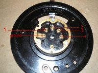
Stator is out of the steering column and laying on my work bench, the self canceling mechanism is on and I'm ready for the next step. Hooking up the four wires, but wait! I see 6 connectors and four wires. Diagram tells me which wire goes to what device but not to which terminal.
In the picture I've labeled the terminals 1 through 4 and I labeled the one I think is ground, ground. Can anyone tell me which wire goes to which terminal? There is also a sixth connection but ISTR that is a mechanical connection and not part of the electrics.
Any help would be greatly appreciated.
Tinkerman